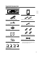
Contents Introduction ..................................... 2 7.1ch Home Theater System HT-S780 AV Receiver (HT-R530) Front Speaker (SKF-530F) Center Speaker (SKC-530C) Surround Speaker (SKM-530S) Surround Back Speaker (SKB-530) Powered Subwoofer (SKW-530) Instruction Manual Connection .................................... 18 Turning On & First Time Setup..... 32 Basic Operation Playing your AV components ....... 34 Using the Tuner............................ 36 Enjoying the Listening Modes .....
WARNING: TO REDUCE THE RISK OF FIRE OR ELECTRIC SHOCK, DO NOT EXPOSE THIS APPARATUS TO RAIN OR MOISTURE. CAUTION: TO REDUCE THE RISK OF ELECTRIC SHOCK, DO NOT REMOVE COVER (OR BACK). NO USER-SERVICEABLE PARTS INSIDE. REFER SERVICING TO QUALIFIED SERVICE PERSONNEL.
Precautions 1. Recording Copyright—Unless it’s for personal use only, recording copyrighted material is illegal without the permission of the copyright holder. 2. AC Fuse—The AC fuse inside the unit is not userserviceable. If you cannot turn on the unit, contact your Onkyo dealer. 3. Care—Occasionally you should dust the unit all over with a soft cloth. For stubborn stains, use a soft cloth dampened with a weak solution of mild detergent and water. Dry the unit immediately afterwards with a clean cloth.
Precautions—Continued Speaker Precautions For Canadian Models Placement NOTE: THIS CLASS B DIGITAL APPARATUS COMPLIES WITH CANADIAN ICES-003. For models having a power cord with a polarized plug: CAUTION: TO PREVENT ELECTRIC SHOCK, MATCH WIDE BLADE OF PLUG TO WIDE SLOT, FULLY INSERT.
Supplied Accessories Make sure you have the following accessories: TUNING / PRESET MASTER VOLUME STANDBY/ON ENTER STANDBY A SPEAKERS B + TONE STEREO LISTENING MODE DISPLAY DIGITAL INPUT RT/PTY/TP MEMORY TUNING MODE RETURN SETUP CLEAR VIDEO 3 INPUT PHONES PURE AUDIO MULTl CH DVD VIDEO 1 VIDEO 2 VIDEO 3 TAPE TUNER CD VIDEO L AUDIO R VCR AV receiver (HT-R530) Subwoofer (SKW-530) (Red) Remote controller & two batteries (AA/R6) (White) Speaker cable for front speakers 15 ft. (4.
Features Amp FM/AM Tuner • • • • • • 30 FM/AM presets • FM/AM auto tuning 7-channel amplifier 110 watts per channel at 8 Ω (FTC) WRAT (Wide Range Amplifier Technology) Optimum gain volume circuitry OptiResponse™ Equalizer (OR-EQ™)*1 function • Preprogrammed for use with other AV components Processing Speaker • Dolby*2 Digital EX and Dolby Pro Logic IIx • DTS, DTS-ES Matrix/Discrete, DTS Neo:6, and DTS 96/24 processing*3 • Cinema Filter function • Linear PCM 192 kHz/24-bit D/A converters on all channel
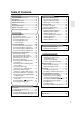
Table of Contents Introduction Important Safety Instructions .......................2 Precautions.....................................................3 Speaker Precautions......................................4 Supplied Accessories ....................................5 Features ..........................................................6 Front & Rear Panels .......................................8 Remote Controller ........................................12 Before Using the AV receiver......................
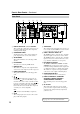
Front & Rear Panels Front Panel North American Model 1 2 3 4 5 6 78 9J K L M TUNING / PRESET MASTER VOLUME STANDBY/ON ENTER STANDBY A SPEAKERS B + TONE STEREO LISTENING MODE DISPLAY DIGITAL INPUT DIMMER RETURN MEMORY TUNING MODE SETUP CLEAR VIDEO 3 INPUT PHONES MULTl CH DVD VIDEO 1 VIDEO 2 VIDEO 3 TAPE TUNER VIDEO CD L AUDIO R VCR N O P Q R S T Other Models U TUNING / PRESET MASTER VOLUME STANDBY/ON ENTER STANDBY A SPEAKERS B + TONE STEREO LISTENING MODE
Front & Rear Panels—Continued K TUNING MODE button (36) Q Input selector buttons (34) This button is used to select the Auto or Manual tuning mode. These buttons are used to select from the following input sources: MULTI CH, DVD, VIDEO 1, VIDEO 2, VIDEO 3, TAPE, TUNER, or CD. L Arrow/TUNING/PRESET & ENTER buttons When the AM or FM input source is selected, the TUNING [ ] [ ] buttons are used to tune the tuner, and the PRESET [ ] [ ] buttons are used to select radio presets (see page 36).
Front & Rear Panels—Continued Rear Panel 1 7 B 8 9 3 4 J 5 K A DIGITAL IN OPTICAL 1, 2, 3 & COAXIAL These optical and coaxial jacks can be used to connect a CD or DVD player and other components with digital audio outputs. B COMPONENT VIDEO A DVD player, TV, or other component that supports component video can be connected here. C AM ANTENNA These push terminals are for connecting an AM antenna. D FM ANTENNA This jack is for connecting an FM antenna.
Front & Rear Panels—Continued Subwoofer (SKW-530) For detailed information, see the pages in parentheses. A STANDBY/ON indicator ■ Front Red: Subwoofer in standby mode Green: Subwoofer on With the Auto Standby function, the SKW-530 automatically turns on when an input signal is detected in Standby mode. When there’s no input signal for a while, the SKW-530 automatically enters Standby mode. B OUTPUT LEVEL control (34) This control is used to adjust the volume of the subwoofer.
Remote Controller How to Use the Remote Controller Including the AV receiver, the remote controller can be used to control up to seven different components. The remote controller has a specific operating mode for use with each type of component. Modes are selected by using the six REMOTE MODE buttons. ■ RECEIVER/TAPE Mode In RECEIVER/TAPE mode, you can control the AV receiver and an Onkyo cassette recorder connected via .
Remote Controller—Continued For detailed information, see the pages in parentheses. A STANDBY button (32) This button is used to set the AV receiver to Standby. B ON button (32) This button is used to turn on the AV receiver. C INPUT SELECTOR buttons (34) These buttons are used to select the input sources. D MULTI CH button (35) This button is used to select the multichannel DVD input. E DIMMER button (38) This button is used to adjust the display brightness.
Remote Controller—Continued A STANDBY button DVD Mode This button sets the DVD player to Standby. To set the remote controller to DVD mode, press the [DVD] REMOTE MODE button. Before selecting DVD mode and starting playback, you should press the [RECEIVER] mode button followed by the [DVD] INPUT SELECTOR button to select the DVD player as the input source. B ON button This button is used to turn on the DVD player.
Remote Controller—Continued A STANDBY button CD/MD/CDR Mode By default, the AV receiver is configured to control an Onkyo CD player. To set the remote controller to CD/MD/CDR mode, press the [CD] REMOTE MODE button. Before selecting CD/MD/CDR mode and starting playback, you should press the [RECEIVER] mode button followed by the [CD] or [TAPE] INPUT SELECTOR button to select the CD player, MiniDisc, or CD recorder as the input source. This button sets the CD player or MD/CD recorder to Standby.
Remote Controller—Continued TAPE Mode TV Control Buttons TAPE mode is used to control an Onkyo cassette recorder connected to the AV receiver via . To set the remote controller to TAPE mode, press the [RECEIVER] REMOTE MODE button. Before selecting TAPE mode and starting playback, you should press the [RECEIVER] REMOTE MODE button followed by the [TAPE] INPUT SELECTOR button to select your cassette recorder as the input source.
Before Using the AV receiver Installing the Batteries 1 To open the battery compartment, press the small hollow and slide open the cover. Using the Remote Controller To use the remote controller, point it at the AV receiver’s remote control sensor, as shown below. Remote control sensor AV receiver STANDBY indicator 2 3 Insert the two supplied batteries (AA/R6) in accordance with the polarity diagram inside the battery compartment. Slide the cover shut. Approx. 16 ft.
Connecting Speakers Enjoying Home Theater You can use two sets of speakers with the AV receiver: speaker set A and speaker set B. Speaker set A (supplied speakers and subwoofer) should be installed in your main listening room and can be used with Dolby Digital and DTS surround material. Each speaker must be positioned at a specific location in your listening room to get the best from surround sound material. The following illustration shows the best positions for your surroundsound speakers.
Connecting Speakers—Continued Speaker Connection Precautions Connecting Speaker Set A Read the following before connecting your speakers: • You can connect speakers with an impedance of 8 ohms or higher. If you use speakers with a lower impedance, and use the amplifier at high volume levels for a long period of time, the built-in protection circuit may be activated. • Disconnect the power cord from the wall outlet before making any connections. • Pay close attention to speaker wiring polarity.
Connecting Antenna This section explains how to connect the supplied indoor FM antenna and AM loop antenna, and how to connect commercially available outdoor FM and AM antennas. The AV receiver won’t pick up any radio signals without any antenna connected, so you must connect the antenna to use the tuner. AM antenna push terminals FM antenna jack Connecting the Indoor FM Antenna The supplied indoor FM antenna is for indoor use only. 1 Attach the FM antenna, as shown.
Connecting Antenna—Continued Connecting an Outdoor FM Antenna Connecting an Outdoor AM Antenna If you cannot achieve good reception with the supplied indoor FM antenna, try a commercially available outdoor FM antenna instead. If good reception cannot be achieved using the supplied AM loop antenna, an outdoor AM antenna can be used in addition to the loop antenna, as shown.
Connecting Your Components AV Connection Color Coding About AV Connections RCA-type AV connections are usually color coded: red, white, and yellow. Use red plugs to connect right-channel audio inputs and outputs (typically labeled “R”). Use white plugs to connect left-channel audio inputs and outputs (typically labeled “L”). And use yellow plugs to connect composite video inputs and outputs. • Before making any AV connections, read the manuals supplied with your other AV components.
Connecting Your Components—Continued Connecting Both Audio & Video By connecting both the audio and video outputs of your DVD player and other AV components to the AV receiver, you can select both the audio and video simultaneously simply by selecting the appropriate input source on the AV receiver. : Signal Flow Video Video Audio Audio TV, projector, etc. DVD player, etc.
Connecting Your Components—Continued Connecting a TV or Projector Step 1: Video Connection Choose a connection type ( A , B , or C ) that matches the TV, and then make the connection. A COMPONENT VIDEO MONITOR OUT V C MONITOR OUT S B Y PB PR COMPONENT VIDEO IN Y PB TV, projector, etc.
Connecting Your Components—Continued Connecting a DVD player Step 1: Video Connection Choose a connection type ( A , B , or C ) that matches the DVD player, and then make the connection. A COMPONENT VIDEO DVD V C S B DVD IN Y IN PB DVD The TV must be connected to the AV receiver with the same type of connection.
Connecting Your Components—Continued Connecting a VCR or DVD Recorder for Playback In addition to video playback, with this hookup example, you can use the VCR’s tuner to listen to the sound of your favorite TV programs via the AV receiver. This is useful if the TV has no audio outputs. Step 1: Video Connection Choose a connection type ( A , B , or C ) that matches the VCR/DVD recorder, and then make the connection. The TV must be connected to the AV receiver with the same type of connection.
Connecting Your Components—Continued Connecting a VCR or DVD Recorder for Recording Step 1: Choose a video connection type ( A or B ) that matches the VCR/DVD recorder, and make the connection. The video source that you want to record must be connected to the AV receiver with the same type of connection. Step 2: Make audio connection a .
Connecting Your Components—Continued Connecting a Satellite, Cable, Set-top box, or Other Video Source Step 1: Video Connection Choose a connection type ( A , B , or C ) that matches the video source, and then make the connection. A V C S B VIDEO 2 COMPONENT VIDEO VIDEO 2 IN Y IN PB VIDEO 2 The TV must be connected to the AV receiver with the same type of connection. PR IN COMPONENT VIDEO OUT Y S VIDEO OUT PB PR Satellite, cable, set-top box, etc.
Connecting Your Components—Continued Connecting a CD Player or Turntable ■ CD Player, or Turntable with Built-in Phono Preamp Step 1: Choose a connection type ( a , b , or c ) that matches the CD player, or choose a for a turntable with a built-in phono preamp, and then make the connection.
Connecting Your Components—Continued Connecting a Cassette, CDR, MiniDisc, or DAT Recorder Step 1: Choose a connection type ( a , b , or c ) that matches the recorder, and then make the connection. b Connect one or the other DIGITAL IN COAXIAL c OUT IN L a OPTICAL 3 R TAPE L L R R IN OUT REC PLAY COAXIAL OUT OPTICAL OUT Cassette recorder, CDR, etc. • With the basic a connection, you can play and record with the recorder, and listen via speaker set B.
Connecting Your Components—Continued Connecting Onkyo Components Step 1: Be sure that the Onkyo component is connected to the AV receiver with an analog audio cable (RCA). Step 2: Make the With connection. (Remote Interactive) you can use the following special functions: Auto Power On/Standby When you start playback on a component connected via , if the AV receiver is in Standby, it will turn on and select that component as the input source automatically.
Turning On STANDBY ON STANDBY/ON STANDBY indicator STANDBY REMOTE MODE ON DVD RECEIVER TAPE/AMP RECEIVER INPUT SELECTOR 1 2 MD CD 3 CDR V1 TUNING / PRESET V2 V3 MASTER VOLUME 4 5 6 MULTI CH DVD TV STANDBY/ON ENTER STANDBY A SPEAKERS B + TONE STEREO LISTENING MODE DISPLAY DIGITAL INPUT RT/PTY/TP MEMORY TUNING MODE RETURN SETUP 7 8 9 TAPE TUNER CD +10 10 CLEAR VIDEO 3 INPUT PHONES PURE AUDIO MULTl CH DVD VIDEO 1 VIDEO 2 VIDEO 3 TAPE TUNER CD VIDEO L AUDIO
First Time Setup Assigning Digital Inputs to Input Sources Changing the TAPE/MD/CDR Display If you connect an -compatible Onkyo MiniDisc recorder or CD recorder to the TAPE IN/OUT jacks, for to work properly, you must change this setting. This setting can only be changed on the AV receiver.
Playing Your AV Components Basic AV Receiver Operation 2 4 DISPLAY TUNING / PRESET ON STANDBY 1 MASTER VOLUME 1 2 V2 4 ENTER STANDBY + TONE STEREO LISTENING MODE DISPLAY DIGITAL INPUT RT/PTY/TP MEMORY TUNING MODE RETURN DVD VIDEO 1 VIDEO 2 VIDEO 3 TAPE TUNER 6 DVD 7 8 TUNER CD +10 0 CLR TV VCR 9 CD VIDEO L AUDIO --/--- R 11 TV SAT 12 DIMMER SLEEP VOL DISC VCR CH CABLE VOL INPUT MULTI CH 1 Subwoofer’s rear panel V3 5 MULTI CH TAPE 10 VIDEO 3 INPUT PH
Playing Your AV Components—Continued Displaying Source Information ON STANDBY REMOTE MODE DVD RECEIVER TAPE/AMP INPUT SELECTOR RECEIVER MD You can display various information about the current input source as follows.
Using the Tuner Listening to the Radio Tuning into Radio Stations ■ Auto Tuning Mode TUNING MODE TUNING TUNING / PRESET 1 TUNING MODE MASTER VOLUME STANDBY/ON ENTER Press the [TUNING MODE] button so that the AUTO indicator appears on the display.
Using the Tuner—Continued Presetting Radio Stations Deleting Presets 2, 4 2 3 TUNING / PRESET TUNING / PRESET MASTER VOLUME STANDBY/ON MASTER VOLUME STANDBY/ON ENTER ENTER STANDBY A SPEAKERS B STANDBY + TONE STEREO LISTENING MODE DISPLAY DIGITAL INPUT RT/PTY/TP MEMORY TUNING MODE RETURN SETUP A SPEAKERS B + TONE STEREO LISTENING MODE DISPLAY DIGITAL INPUT RT/PTY/TP MEMORY TUNING MODE CLEAR RETURN SETUP CLEAR VIDEO 3 INPUT PHONES PURE AUDIO MULTl CH DVD VIDEO 1 VIDEO 2
Common Functions This chapter explains functions that can be used with any input source. ON STANDBY REMOTE MODE Press [RECEIVER] first DVD RECEIVER TAPE/AMP INPUT SELECTOR MD 1 2 3 V1 V2 V3 4 5 6 MULTI CH DVD CD CDR DIMMER 7 8 9 TAPE TUNER CD +10 0 10 --/--- VOL DISC 1 Press the AV receiver’s [TONE] button repeatedly to select either Bass or Treble.
Common Functions—Continued Using the Sleep Timer Adjusting Speaker Levels With the sleep timer, you can set the AV receiver so that it automatically turns off after a set period. Press the remote controller’s [SLEEP] button repeatedly to select the required sleep time. You can set the sleep time from 90 to 10 minutes in 10 minute steps. The SLEEP indicator appears on the display when the sleep timer has been set, as shown.
Using the Listening Modes Selecting with the Remote Controller Selecting Listening Modes TV See “About the Listening Modes” on page 42 for detailed information about the listening modes. • The Dolby Digital and DTS listening modes can only be selected if your DVD player is connected to the AV receiver with a digital audio connection (coaxial or optical). • Listening mode availability depends on the format of the current input signal.
Using the Listening Modes—Continued The following table lists all the listening modes and shows which modes can be selected for each input signal format. DTS/DTS 96/24*2 Dolby D Analog, PCM*1 Input signal format Source Listening mode */2 CD, TV, VHS, MD, turntable, radio, cassette, DTV, etc. 2/0 1/0,1+1 (Stereo) Other 3/2.1 DVD, DTV, etc. DTS-ES 2/0 (Stereo) Discrete Matrix DVD, CD, etc.
Using the Listening Modes—Continued About the Listening Modes Dolby Pro Logic IIx With its built-in surround-sound decoders and DSP programs, the AV receiver can transform your home listening room into a movie theater or concert hall. If you’ve connected surround back speakers to the AV receiver, Dolby Pro Logic IIx allows you to enjoy 7.1channel playback from 2-channel or 5.1-channel music or movies.
Using the Listening Modes—Continued DTS-ES Matrix This is DTS with an added surround back channel for 6.1 surround sound. Use it to provide 6.1 channel surround playback with program material recorded in DTS 5.1 format. Since DTS 5.1 program material contains surround back channel information, all channels can be reconstructed for 6.1-channel playback. Use this mode with CDs and DVDs that bear the DTS-ES or DTS logo. Neo:6 This mode provides 6.1-channel playback from 2-channel sources.
Adjusting the Listening Modes Using the CinemaFILTER ON STANDBY REMOTE MODE DVD RECEIVER RECEIVER TAPE/AMP INPUT SELECTOR MD 1 2 3 V1 V2 V3 CD CDR 4 5 6 MULTI CH DVD 7 8 TAPE TUNER CD +10 0 CLR 10 --/--- TV TV VCR 9 11 SAT 12 DIMMER SLEEP VOL DISC CH CABLE VOL 1 INPUT GUIDE TOP MENU PREVIOUS MENU SP A / B ENTER With the CinemaFILTER, you can soften overly bright movie soundtracks, which are typically mixed for reproduction in a movie theater.
Adjusting the Listening Modes—Continued 3 Use the Left and Right [ ]/[ ] buttons to change the settings. Press the Down [ ] button to select the next setting. 4 Repeat step 3 to complete all settings. 5 Press the [SETUP] button. Setup closes. If the stereo image feels too wide, or there’s too much surround sound, move the sound field forward to improve the balance. Conversely, if the stereo image feels like it’s in mono, or there’s not enough surround sound, move it backward.
Advanced Setup Advanced Speaker Settings 3 Use the Up and Down [ ]/[ ] buttons to select “2. Sp Distance,” and then press the [ENTER] button. 4 While “Unit” is displayed, use the Left and Right [ ]/[ ] buttons to select “feet” or “meters”. feet: Distances in feet. Can be set from 1 to 30 feet in 1-foot steps. meters: Distances in meters. Can be set from 0.3 to 9 meters in 0.3-meter steps.
Advanced Setup—Continued Speaker Levels With this function, you can adjust the volume of each speaker so that all speakers can be heard equally at the listening position. Speaker levels cannot be adjusted while the AV receiver is muted. 1 Press the [RECEIVER] button followed by the [SETUP] button on the remote controller. 2 Use the Up and Down [ ]/[ ] buttons to select “3. Level Cal,” and then press the [ENTER] button. A pink noise test tone is output by the front left speaker.
Advanced Setup—Continued Speaker Configuration, Crossover Frequency, and Double Bass settings only need to be changed if you’re not using the speakers in this package. 4 Speaker Configuration This section explains how to specify which speakers are connected and their sizes. For speakers with a cone diameter larger than 6-1/2 inches (16 cm), specify Large. For those with a smaller diameter, specify Small.
Advanced Setup—Continued 7 8 Use the Down [ ] button to select “Surr Back,” and use the Left and Right [ ]/[ ] buttons to select Small, Large, or None. Small: Select if the surround back speakers are small. Large: Select if the surround back speakers are large. None: Select if no surround back speakers are connected. Notes: • If the Surround setting in step 6 is set to None, this setting does not appear. • If the Surround setting in step 6 is set to Small, the Large option cannot be selected.
Advanced Setup—Continued Digital Input Signal Formats The following table shows the display indicators for each supported digital signal format. Format Display Dolby Digital DTS PCM PCM Normally, the AV receiver detects the signal format automatically. However, if you experience either of the following issues when playing PCM or DTS material, you can manually set the signal format to PCM or DTS: • If the beginnings of tracks from a PCM source are cut off, try setting the format to PCM.
Recording This chapter explains how to record the selected input source to an AV component with recording capability, and how to record audio and video from two different sources. Recording the Input Source You can record only to AV components that are connected to the TAPE OUT or VIDEO 1 OUT jacks. See pages 22–31 for information on connecting your AV components to the AV receiver.
Controlling Other Components You can use the AV receiver’s remote controller (RC-608M) to control your other components, including those made by other manufacturers. This chapter explains how to enter the necessary remote control code for the component that you want to control (e.g., DVD player, TV, or VCR). 2 While holding down the REMOTE MODE button that you want to set, press the [DISPLAY] button for 3 seconds. The REMOTE MODE button lights up.
Controlling Other Components—Continued Remote Control Codes for Onkyo Components Connected via Onkyo components that are connected via can be controlled by pointing the remote controller at the AV receiver. This means that you can control such components even if they are out of sight, for example, installed in a rack. 1 Make sure the Onkyo component is connected with an cable and an analog audio cable (RCA). See page 31 for details.
Controlling Other Components—Continued To control another component, point the remote controller at it and use the buttons explained below. (You must select the appropriate remote control mode first.
Troubleshooting If you have any trouble using the AV receiver and speakers, look for a solution in this section. If you can’t resolve the issue yourself, contact your Onkyo dealer. Power Can’t turn on the AV receiver? • Make sure that the power cord is properly plugged into the wall outlet. • Unplug the power cord from the wall outlet, wait five seconds or more, then plug it in again. The AV receiver turns off as soon as it’s turned on? • The amp protection circuit has been activated.
Troubleshooting—Continued The subwoofer produces no sound? • The level of the input signal was too low so the subwoofer entered Standby mode. Increase the subwoofer level slightly on the HT-R530. • Make sure that the subwoofer’s [POWER] switch is set to ON (not North American models). • The subwoofer’s OUTPUT LEVEL control is set at minimum. Turn it up. • The subwoofer outputs no sound while only speaker set B is on. Turn on speaker set A.
Troubleshooting—Continued Remote Controller The remote controller doesn’t work? • Make sure that the batteries are installed with the correct polarity (page 17). • Make sure that the remote controller is not too far away from the AV receiver, and that there’s no obstruction between the remote controller and the AV receiver’s remote control sensor (page 17). • Make sure you’ve selected the correct remote controller mode (page 12). • Make sure you’ve entered the correct remote control code.
Specification ■ AV Receiver (HT-R530) Amplifier Section General Power Output 2 channel driven: Power Supply Dynamic Power THD (Total Harmonic Distortion) Damping Factor Input Sensitivity and Impedance Output Level and Impedance Frequency Response Tone Control Signal to Noise Ratio Speaker Impedance North American: 110 W + 110 W (8Ω, 1 kHz, FTC) European: 110 W + 110 W (8Ω, 1kHz, DIN) Ohters: 130 W + 130 W (8Ω, 1kHz, JEITA) 230 W + 230 W (3Ω,Front) 170 W + 170 W (4Ω,Front) 120 W + 120 W (8Ω,Front) 0.
Specification—Continued ■ Speaker ■ Powered Subwoofer (SKW-530) ■ Center Speaker (SKC-530C) Type: Bass-reflex Input sensitivity/impedance: 330 mV / 100 kΩ Maximum output power: 230 W (Dynamic Power) Frequency response: 25 Hz–150 Hz Cabinet capacity: 1.36 cubic feet (38.5 L) Dimensions (W × H × D): 10-13/16" × 20-3/8" × 16-3/16" (275 × 518 × 411 mm) Weight: 30 lbs. (13.
Sales & Product Planning Div. : 2-1, Nisshin-cho, Neyagawa-shi, OSAKA 572-8540, JAPAN Tel: 072-831-8023 Fax: 072-831-8124 ONKYO U.S.A. CORPORATION 18 Park Way, Upper Saddle River, N.J. 07458, U.S.A. Tel: 201-785-2600 Fax: 201-785-2650 http://www.us.onkyo.com/ ONKYO EUROPE ELECTRONICS GmbH Liegnitzerstrasse 6, 82194 Groebenzell, GERMANY Tel: +49-8142-4401-0 Fax: +49-8142-4401-555 http://www.eu.onkyo.