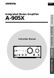
English A-905X Before using Integrated Stereo Amplifier Connections Preparations Instruction Manual INTEGRATED STEREO AMPLIFIER VOLUME WIDE RANGE AMP TECHNOLOGY INPUT MD TUNER TAPE LINE-1/ DVD LINE-2 STANDBY DIRECT BASS POWER ON TREBLE BALANCE PHONES SOURCE DIRECT DIRECT TONE OFF − + − + L R ACOUSTIC PRESENCE OFF/1/2 Operation CD STANDBY/ON A-905X Other Information
Before using Thank you for purchasing ... Thank you for purchasing the ONKYO A-905X Integrated Stereo Amplifier. Please read this manual thoroughly before making any connection or turning on the power. Follow these instructions to obtain optimum performance and maximum listening enjoyment from your new A-905X. Please retain this manual for future reference.
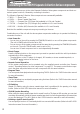
Important Safeguards 1. Read Instructions – All the safety and operating instructions should be read before the appliance is operated. 2. Retain Instructions – The safety and operating instructions should be retained for future reference. Heed Warnings – All warnings on the appliance and in the operating instructions should be adhered to. 4. Follow Instructions – All operating and use instructions should be followed. 5.
Precautions 1. Warranty Claim You can find the serial number on the rear panel of this unit. In case of warranty claim, please report this number. For British model Replacement and mounting of an AC plug on the power supply cord of this unit should be performed only by qualified service personnel. 2. Recording Copyright Recording of copyrighted material for other than personal use is illegal without permission of the copyright holder.
Table of contents Connections Connecting to the ONKYO Separate Collection Series components .... 6 Connecting to components other than the Separate Collection Series .... 11 Connecting speaker systems ............................................................ 14 Connecting the AC power cord (mains lead) .................................... 16 Preparing the remote controller ........................................................ 17 Operation Turning the unit on .........................................
Connections Connecting to the ONKYO Separate Collection Series components This section introduces you to the other Separate Collection Series system components and their convenient system functions, followed by connecting instructions. The following Separate Collection Series components are commercially available: • T-405X ........ Stereo Tuner • K-505X ....... Stereo Cassette Tape Deck • C-705X ....... Compact Disc (CD) Player (Not available in U.S.A and Canada) • C-707CH ....
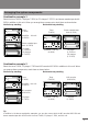
Arranging the system components Combination example 1 Select the tuner T-405X, CD player C-705X (or CD changer C-707CH), and stereo cassette tape deck K505X in addition to this unit. When you arrange these components, stack them as shown below.
Connecting to the ONKYO Separate Collection Series components Connecting to the audio connector Before connecting • Do not connect the unit’s AC power cord (mains lead) to a wall outlet (the mains) until you have completed all the other connections, including and AC OUTLET connections on page 10. Refer to “Connecting to components other than the Separate Collection Series” on page 11 and “Connecting speaker systems” on page 14.
Connections for combination example 1 OUT(REC) IN(PLAY) OUT(REC) OUTPUT L L L IN(PLAY) L L SPEAKERS MODEL NO. FM STEREO TUNER T-405X OUTPUT LINE-2 TAPE LINE-1 OUT(REC) L L FM 75 ANTENNA R R A-905X R R AC OUTLET TUNER LINE-2 OUT(REC) Tuner (T-405X) CD AC230V 50Hz SWITCHED 100W MAX. SUBWOOFER PRE OUT IN OUT MD PROCESSOR TAPE LINE-1 IN(PLAY) Amplifier – this unit (A-905X) L R TUNER ANALOG OUTPUT MODEL NO.
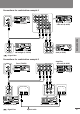
Connecting to the ONKYO Separate Collection Series components Connecting the connectors and AC OUTLETS Before connecting • The hookups on page 8 or 9 are needed in addition to the (for remote control operations) and AC OUTLET (for power supply to each component) hookups on this page. • Each component has two connectors. There is no difference between those connectors. The components may be connected in any order.
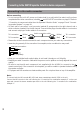
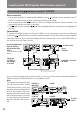
Connecting to components other than the Separate Collection Series Connecting audio/video equipment to audio cables Audio connection cable To L connector (White) (White) To L connector To R connector (Red) (Red) To R connector Improper connection Connections Insert completely LD player AUDIO OUT REC INPUT AUDIO OUT Amplifier – this unit (A-905X) IN(PLAY) L OUT(REC) L IN(PLAY) L L R R SPEAKERS R R LINE-2 TAPE LINE-1 OUT(REC) Operation OUT(REC) L PLAY OUTPUT INTEGRATED STER
Connecting to components other than the Separate Collection Series Connecting a sound processor You can connect a sound processor (e.g. graphic equalizer, surround processor, etc.) to the unit. Before connecting • Disconnect the jumper plugs using the PROCESSOR connectors. – Please retain them for future use. – Never connect the jumper plugs to the other connectors, as this may cause the unit to malfunction, so that the sound is not reproduced.
Connecting the cables If your other components are made by ONKYO and those components are equipped with -connected components with the supplied remote controller. tors, you can control the connec- The illustration below is an example of a hookup. Connections Connections Tuner Before using Before connecting • The unit must be connected in the system hookups for control operations. connectors. There is no difference between these connectors.
Connecting speaker systems Connecting left and right speakers Before connecting • The load impedance of each speaker must be at least 4 ohms. • Do not use unnecessarily long or extremely thin speaker cords. Otherwise, the DC resistance of the speaker cords may become too high, lowering the damping factor and causing the sound quality to deteriorate. • Do not connect the speaker cord to the L and R connectors at the same time and do not connect two or more speakers to the same speaker connectors.
Connecting a sub-woofer Connections This unit OUT(REC) L IN(PLAY) L L R R SPEAKERS LINE-2 TAPE LINE-1 OUT(REC) INTEGRATED STEREO AMPLIFIER MODEL NO. RATING; REMOTE CONTROL IN(PLAY) A-905X R AC OUTLET CD MD OUT IN PROCESSOR AC230V 50Hz SWITCHED 100W MAX.
Connecting the AC power cord (mains lead) INTEGRATED STEREO AMPLIFIER VOLUME WIDE RANGE AMP TECHNOLOGY INPUT CD STANDBY/ON MD TUNER TAPE LINE-1/ DVD LINE-2 STANDBY DIRECT BASS POWER ON TREBLE SOURCE DIRECT DIRECT BALANCE PHONES TONE OFF − + − + L ACOUSTIC PRESENCE OFF/1/2 R A-905X POWER switch STANDBY indicator 1 Connect the AC power cord (mains lead) to the wall outlet (the mains).
Preparations Preparing the remote controller Installing the remote controller batteries 1 Remove the battery compartment Point the remote controller toward the remote control sensor. The STANDBY indicator lights up when the unit receives a signal from the remote controller.
Operation Turning the unit on INPUT SELECTOR POWER INTEGRATED STEREO AMPLIFIER VOLUME WIDE RANGE AMP TECHNOLOGY INPUT MD CD STANDBY/ON TUNER LINE-1/ DVD TAPE LINE-2 STANDBY DIRECT BASS POWER TREBLE SOURCE DIRECT DIRECT BALANCE PHONES TONE Power/muting lamp VOLUME ACOUSTIC PRESENCE G.
Choosing the required source INPUT SELECTOR POWER Input source indicators G.
Adjusting the sound INPUT SELECTOR POWER ACOUSTIC PRESENCE INTEGRATED STEREO AMPLIFIER VOLUME WIDE RANGE AMP TECHNOLOGY G.
Muting/Listening through the headphones INPUT SELECTOR POWER G.
Recording INPUT SELECTOR POWER Input source indicators VOLUME INTEGRATED STEREO AMPLIFIER VOLUME G.
Other Information Troubleshooting If you have any problems with the unit, please check the troubleshooting table below first. For any problems not covered in the table, please consult your nearest ONKYO authorized service center. Cause Remedy The unit doesn’t turn on. The AC power cord is not fully inserted into the wall outlet. Insert the AC power cord (mains lead) plug into the wall outlet (the mains) securely. Sound is reproduced from neither left or right speaker.
Specifications Power output 15 watts per channel, min RMS, at 8 ohms, both channels driven 1 kHz, with no more than 0.2% THD 2 × 20 watts at 4 ohms, 1 kHz (DIN) 2 × 15 watts at 8 ohms, 1 kHz (DIN) Total harmonic distortion 0.2% at rated power IM distortion 0.2% at rated power Damping factor 30 at 8 ohms Frequency and response 15 to 30,000 Hz ± 1 dB Input sensitivity/impedance TUNER/CD/LINE: 180 mV/50 kohms TAPE PLAY: 180 mV/50 kohms MD PLAY: 180 mV/50 kohms Output sensitivity/impedance TAPE REC: 180 mV/2.
Index to parts and controls For operational instructions, refer to the page indicated in square parentheses. Rear panel AC power cord (mains lead) [16] connectors [10, 13] LINE-1 jacks [11] LINE-2 jacks [11] OUT(REC) L IN(PLAY) L L SPEAKERS INTEGRATED STEREO AMPLIFIER MODEL NO. RATING; R R REMOTE CONTROL IN(PLAY) TAPE LINE-1 OUT(REC) A-905X R SPEAKERS connectors [14] SUBWOOFER PRE OUT jack [15] L R AC OUTLET TUNER CD AC230V 50Hz SWITCHED 100W MAX.
Index to parts and controls Remote control – The unit operation buttons INPUT SELECTOR POWER POWER button [18] G.
Remote control – Operating buttons for other components Clock/Sleep timer control • CLOCK CALL : Clock call button • SLEEP : Sleep timer button INPUT SELECTOR POWER G.
Sales & Product Planning Div. : 2-1, Nisshin-cho, Neyagawa-shi, OSAKA 572-8540, JAPAN Tel: 072-831-8111 Fax: 072-833-5222 http://www.onkyosa.com ONKYO U.S.A. CORPORATION 18 Park Way, Upper Saddle River, N.J. 07458, U.S.A. Tel: 201-785-2600 Fax: 201-785-2650 http://www.onkyousa.com ONKYO EUROPE ELECTRONICS GmbH Liegnitzerstrasse 6, 82194 Groebenzell, GERMANY Tel: 49-8142-4401-0 Fax: 49-8142-4401-555 http://www.onkyo.