Contents AV Controller PR-SC5508 Introduction ...................................2 Connections.................................13 Turning On & Basic Operations ......25 Instruction Manual Advanced Operations .................43 Controlling iPod & Other Components............................81 Others...........................................94 Thank you for purchasing an Onkyo AV Controller. Please read this manual thoroughly before making connections and plugging in the unit.
Introduction WARNING: TO REDUCE THE RISK OF FIRE OR ELECTRIC SHOCK, DO NOT EXPOSE THIS APPARATUS TO RAIN OR MOISTURE. CAUTION: TO REDUCE THE RISK OF ELECTRIC SHOCK, DO NOT REMOVE COVER (OR BACK). NO USER-SERVICEABLE PARTS INSIDE. REFER SERVICING TO QUALIFIED SERVICE PERSONNEL.
Precautions 1. Recording Copyright—Unless it’s for personal use only, recording copyrighted material is illegal without the permission of the copyright holder. 2. AC Fuse—The AC fuse inside the unit is not user-serviceable. If you cannot turn on the unit, contact your Onkyo dealer. 3. Care—Occasionally you should dust the unit all over with a soft cloth. For stubborn stains, use a soft cloth dampened with a weak solution of mild detergent and water. Dry the unit immediately afterwards with a clean cloth.
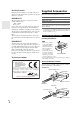
Supplied Accessories For British models Replacement and mounting of an AC plug on the power supply cord of this unit should be performed only by qualified service personnel.
Contents Introduction Important Safety Instructions ......................................... 2 Precautions....................................................................... 3 Supplied Accessories...................................................... 4 Using the Remote Controller .......................................... 4 Features ............................................................................ 6 Front & Rear Panels......................................................... 8 Front Panel...
Features Processing Miscellaneous • THX Ultra2 Plus*1 Certified • HQV-Reon-VX Video Processing with 1080p Video Upscaling of All Video Sources via HDMI • HDMI (Ver.1.4a with Audio Return Channel, 3D), Deep Color, x.v.
*10 *1 HD Radio™ and the HD Radio Ready logo are proprietary trademarks of iBiquity Digital Corporation. To receive HD Radio broadcasts, you must install an Onkyo UP-HT1 HD Radio tuner module (sold separately). THX and the THX logo are trademarks of THX Ltd. which may be registered in some jurisdictions. All rights reserved. *2 “x.v.Color” is a trademark of Sony Corporation. *11 *3 Manufactured under license under U.S.
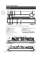
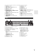
Front & Rear Panels Front Panel b cd a h e i f j g Front flap Pull here to open the flap. The actual front panel has various logos printed on it. They are not shown here for clarity. The page numbers in parentheses show where you can find the main explanation for each item.
The page numbers in parentheses show where you can find the main explanation for each item.
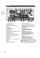
Rear Panel a bc d p f g e q r h i s u l m n o v w r 12V TRIGGER OUT (A/B/C) jacks b IR IN (A/B) and OUT jacks s Composite video, S-Video and analog audio jacks (BD/DVD IN, VCR/DVR IN and OUT, CBL/SAT IN, GAME IN, PC IN, TAPE IN and OUT, TV/CD IN and PHONO IN) d USB port e ETHERNET port f u REMOTE CONTROL jack g RS232 terminal Terminal for control.
Remote Controller Controlling the AV Controller To control the AV controller, press RECEIVER to select Receiver mode. You can also use the remote controller to control Onkyo Blu-ray Disc/DVD player, CD player and other components. See “Entering Remote Control Codes” for more details (➔ 88). a b i c d For detailed information, see the pages in parentheses.
About Home Theater Enjoying Home Theater Thanks to the AV controller’s superb capabilities, you can enjoy surround sound with a real sense of movement in your own home—just like being in a movie theater or concert hall. With Blu-ray Discs or DVDs, you can enjoy DTS and Dolby Digital. With analog or digital TV, you can enjoy Dolby Pro Logic IIx, DTS Neo:6, or Onkyo’s original DSP listening modes. You can also enjoy THX Surround EX (THX-certified THX speaker system recommended).
Connections Connecting the AV Controller Connecting Your Speakers The AV controller is designed to be used with a separate multichannel power amplifier. You connect the AV controller’s PRE OUT jacks to the amplifier’s inputs, and connect your speakers to the amplifier’s speakers terminals. Speaker settings such as crossover frequency and distance are set on the AV controller. Speaker Configuration The following table indicates the channels you should use depending on the number of speakers that you have.
Note *1 *2 Specify crossover frequency for the channel that you want to output in “Speaker Configuration” (➔ 48). If you use the front high and wide speakers at the same time, you need to set the “Front High + Front Wide” setting to “Yes” (➔ 48). Connecting a Power Amplifier with XLR Inputs You can connect the AV controller to a multichannel power amplifier with balanced XLR input jacks by using several XLR audio cables. The AV controller’s balanced PRE OUT jacks are wired as shown.
Using Dipole Speakers You can use dipole speakers for the surround and surround back speakers. Dipole speakers output the same sound in two directions. Dipole speakers typically have an arrow printed on them to indicate how they should be positioned. The surround dipole speakers should be positioned so that their arrows point toward the TV/screen, while the surround back dipole speakers should be positioned so that their arrows point toward each other, as shown.
Bi-amping the Front Speakers The FRONT L/R and SURR BACK L/R outputs can be used with front speakers and surround back speakers, respectively, or bi-amped to provide separate tweeter and woofer feeds for a pair of front speakers that support bi-amping, providing improved bass and treble performance. • When bi-amping is used, the AV controller is able to feed up to 7.2 speakers in the main room. • For bi-amping, the FRONT L/R outputs feed the front speakers’ woofer terminals.
Connecting a Balanced Audio Source You can connect a balanced audio source to the AV controller’s BALANCE L/R INPUT jacks by using two XLR audio cables. To use the balanced input, you must assign it to an input selector (➔ 47). If you connect a mono source, use the BALANCE L INPUT jack and set the “Input Channel” setting to “Mono(L)” (➔ 47). The AV controller’s balanced INPUT jacks are wired as shown.
About AV Connections Connected image with AV components HDMI cable Other cables : Video & Audio Blu-ray Disc/ DVD player : Audio AV controller AV controller TV, projector, etc. : Video Game console TV, projector, etc. Blu-ray Disc/ DVD player • Before making any AV connections, read the manuals supplied with your AV components. • Don’t connect the power cord until you’ve completed and double-checked all AV connections.
Note • The AV controller does not support SCART plugs. • The AV controller’s optical digital jacks have shutter-type covers that open when an optical plug is inserted and close when it’s removed. Push plugs in all the way. Caution • To prevent shutter damage, hold the optical plug straight when inserting and removing. Connecting Your Components with HDMI VCR or DVD recorder/Digital Video Recorder Game console TV, projector, etc.
Connecting Your Components Front A C E Rear B D F G Connect your components to the appropriate jacks. The default input assignments are shown below. ✔: Assignment can be changed (➔ 46, 47). No. Jack A AUX INPUT B C COMPONENT VIDEO DIGITAL VIDEO Components Composite video Camcorder, etc AUDIO L/R Analog audio DIGITAL Digital audio IN 1 (BD/DVD) Component video Blu-ray Disc/DVD player ✔ Satellite, cable, set-top box, etc.
Note *1 Connect a turntable (MM) that has built-in a phono preamp to TV/CD IN or connect it to PHONO IN with the phono preamp turned off. If your turntable (MM) doesn’t have a phono preamp, connect to PHONO IN. If your turntable has a moving coil (MC) type cartridge, you’ll need a commercially available MC head amp or MC transformer to connect to PHONO IN. See your turntable’s manual for details. If your turntable has a ground wire, connect it to the AV controller’s GND screw.
Connecting Antenna This section explains how to connect the supplied indoor FM antenna and AM loop antenna. The AV controller won’t pick up any radio signals without any antenna connected, so you must connect the antenna to use the tuner. Caution (North American models) Insert the plug fully into the jack. (European and Asian models) • Be careful that you don’t injure yourself when using thumbtacks. Insert the plug fully into the jack. Push. Insert wire. Release. Assembling the AM loop antenna.
Which Connections Should I Use? The AV controller supports several connection formats for compatibility with a wide range of AV equipment. The format you choose will depend on the formats supported by your components. Use the following sections as a guide. Video Connection Formats Video component can be connected by using any one of the following video connection formats: composite video, S-Video, PC IN (Analog RGB), component video or HDMI, the latter offering the best picture quality.
■ “Monitor Out” setting set to “Analog” Video input signals flow through the AV controller as shown, with composite video, S-Video and PC IN (Analog RGB) sources being upconverted for the component video output. Use this setting if you connect the AV controller’s COMPONENT VIDEO MONITOR OUT to your TV. Composite video is upconverted to S-Video and S-Video is downconverted to composite video. Note that these conversions only apply to the MONITOR OUT V and S outputs, not the VCR/DVR OUT V and S outputs.
Turning On & Basic Operations Turning On/Off the AV Controller (North American models) ON/STANDBY STANDBY indicator (European and Asian models) ON/STANDBY STANDBY indicator STANDBY ON RECEIVER POWER Turning On 1 2 (European and Asian models) Set POWER to the ON position ( ) on the front panel. The AV controller enters Standby mode, and the STANDBY indicator comes on. Press ON/STANDBY on the front panel. or Press RECEIVER followed by ON on the remote controller.
Basic Operations This manual describes the procedure using the remote controller unless otherwise specified. Selecting the Language Used for the Onscreen Setup Menus Displaying Source Information You can display various information about the current input source as follows. (Components connected to the UNIVERSAL PORT jack are excluded.) Press RECEIVER followed by DISPLAY repeatedly to cycle through the available information. You can determine the language used for the onscreen setup menus.
Muting the AV Controller 2 Use q/w/e/r to make the desired selection. ■ Audio `Performs audio settings. For details, refer to “Using the Audio Settings” (➔ 62). You can temporarily mute the output of the AV controller. Press RECEIVER followed by MUTING. The output is muted and the MUTING indicator flashes on the display. ■ Video*1 `You can change the following settings: “Wide Mode”, “Picture Mode”, “Brightness”, “Contrast”, “Hue” and “Saturation”.
Changing the Input Display When you connect an u-capable Onkyo component, you must configure the input display so that u can work properly. This setting can be done only from the front panel. 1 Press TAPE, GAME or VCR/DVR so that “TAPE”, “GAME” or “VCR/DVR” appears on the display. Using ACTIVITIES to Start Easy Macros You can use ACTIVITIES to execute a number of remote control operations with a single button. This button has the following two modes.
Turning Off the Components Press ALL OFF. The playback component assigned to the lastpressed ACTIVITIES, the AV controller, and the TV turn off.*2 *2 When the last-pressed ACTIVITIES is MY MUSIC, the TV will not turn off. Changing the Playback Components Assigned to ACTIVITIES You can change the playback components assigned to the ACTIVITIES of Easy Macro mode using the following procedure.
4 TV Caution def cab • When the “Subwoofer” setting is set to “1ch”, the lefthand subwoofer (SW1) alone will be measured. When the “Subwoofer” setting is set to “1ch” with two subwoofers connected, the right-hand subwoofer (SW2) will not be measured and no sound will be output. • An error will occur if you set “Subwoofer” to “2ch” without connecting any subwoofers, or with only one subwoofer connected. gh : Listening area a to h: Listening position Note • Make the room as quiet as possible.
Tip Note 9 • You can view the calculated settings for the speaker configuration, speaker distances, and speaker levels by using e/r. Disconnect the speaker setup microphone. Note • When Audyssey MultEQ® XT32 Room Correction and Speaker Setup is complete, the “Equalizer” will be set to “Audyssey” (➔ 50). The Audyssey indicator will light (➔ 9). • You can cancel Audyssey MultEQ XT32 Room Correction and Speaker Setup at any point in this procedure simply by disconnecting the setup microphone.
Listening to the Radio This section describes the procedure using the buttons on the front panel unless otherwise specified. ■ Manual tuning mode 1 2 Using the Tuner With the built-in tuner you can enjoy AM and FM radio stations. You can store your favorite stations as presets for quick selection. You can change the frequency steps (➔ 60). Press and hold TUNING q/w. The frequency stops changing when you release the button. Press the buttons repeatedly to change the frequency one step at a time.
Presetting FM/AM Stations You can store a combination of up to 40 of your favorite FM/AM radio stations as presets. 1 2 3 4 Tune into the FM/AM station that you want to store as a preset. See the previous section. When tuned into an RDS station, the RDS indicator lights. What is RDS? (Actual display depends on the country.) RDS stands for Radio Data System and is a method of transmitting data in FM radio signals.
Finding Stations by Type (PTY) ■ RDS program types (PTY) You can search for radio stations by type. Type Display None None Press RT/PTY/TP twice. The current program type appears on the display. News reports News Current affairs Affairs Use PRESET e/r to select the type of program you want. See the table shown later in this chapter. Information Info To start the search, press ENTER.
Recording This section explains how to record the selected input source to a component with recording capability, and how to record audio and video from different sources. Connecting a Recording Component 3 On the source component, start playback. If you select another input source during recording, that input source will be recorded. Recording Separate AV Sources L R AUDIO IN VCR, DVD recorder VIDEO IN Cassette, CDR, MD, etc.
Using the Listening Modes Selecting Listening Modes See “About Listening Modes” for detailed information about the listening modes (➔ 37). Listening Mode Buttons Press RECEIVER first. PURE AUDIO MUSIC MOVIE/TV MOVIE/TV, MUSIC, GAME, THX GAME THX MOVIE/TV button This button selects the listening modes intended for use with movies and TV. MUSIC button This button selects the listening modes intended for use with music.
About Listening Modes The AV controller’s listening modes can transform your listening room into a movie theater or concert hall, with high fidelity and stunning surround sound. Explanatory Notes ij ab c LISTENING MODE de gh kl f a b Front speakers c Center speaker d e Surround speakers f Subwoofer(s) g h Surround back speakers i j Front high speakers k l Front wide speakers ■ Input Source The following audio formats are supported by the listening mode. A This is mono (monophonic) sound.
Listening Modes Listening Mode Description Input Source Pure Audio*1 In this mode, the display and video circuitry are turned off, minimizing pos- A sible noise sources for the ultimate in high-fidelity audio reproduction. (As S Pu r eAAu d i o the video circuitry is turned off, only video signals input through HDMI D input can be output from an HDMI output(s). F Direct In this mode, audio from the input source is output without surround-sound G processing.
Listening Mode Description Input Source Speaker Layout DTS-HD High Resolution Audio (Continued from the previous page.) D xcn m F xcn*2 m*2 D xcn F xcn*2 m*2 S D xcn m D xcn m D xcn m This mode is for use with DTS-ES Discrete soundtracks, which use a disG crete surround back channel for true 6.1/7.1-channel playback. The seven totally separate audio channels provide better spatial imaging and 360degree sound localization, perfect for sounds that pan across the surround channels.
Listening Mode THX THX N TH eX o THX N TH eX o THX THX THX Description Input Source Founded by George Lucas, THX develops stringent standards that ensure D movies are reproduced in movie theaters and home theaters just as the direc- F C i n ema tor intended. THX Modes carefully optimize the tonal and spatial character- G istics of the soundtrack for reproduction in the home-theater environment. :M 6 ut sr i cx t e x t e They can be used with 2-channel matrixed and multichannel sources.
Listening Mode Description Input Source Neural Surround*5 This mode employs psychoacoustic frequency domain processing, which S allows delivery of a more detailed sound stage, with superior channel separaNR L S u r r o u n d tion and localization of audio elements. The Neural Surround modes can expand any 2-channel stereo source for 5.1- or 7.1-channel playback, respec- D NR L T HX C i n ema tively.
Onkyo-Original DSP Listening Modes Listening Mode Description Orchestra Suitable for classical or operatic music, this mode emphasizes the surround A channels in order to widen the stereo image, and simulates the natural rever- S beration of a large hall. D Suitable for acoustic instruments, vocals, and jazz, this mode emphasizes the F front stereo image, giving the impression of being right in front of the stage.
Advanced Operations Advanced Setup On-screen Setup Menus Common Procedures in Setup Menu This manual describes the procedure using the remote controller unless otherwise specified. RECEIVER MENU a b c d e f g h i 1. 2. 3. 4. 5. 6. 7. 8. 9. a Input/Output Assign (➔ 44) f Miscellaneous (➔ 59) 1. Input/Output Assign 1. 2. 3. 4. 5. Monitor Out HDMI Input Component Video Input Digital Audio Input Analog Audio Input b Speaker Setup (➔ 48) 6. Miscellaneous 1. 2. 3. 4. 5.
Explanatory Notes a b c Note Main Menu Speaker Setup ■ Subwoofer ` 1ch: Audio signal is outputted from SW1 jack only. ` 2ch: Audio signal is outputted from SW1 and SW2 jacks.
■ Resolution You can specify the output resolution for the HDMI output and COMPONENT VIDEO MONITOR OUT and have the AV controller upconvert the picture resolution as necessary to match the resolution supported by your TV. `Through*1: Select this to pass video through the AV controller at the same resolution and with no conversion. `Auto*2: Select this to have the AV controller automatically convert video at resolutions not supported by your TV.
Note • For composite video, S-Video, and component video upconversion for the HDMI output, the “Monitor Out” setting must be set to other than “Analog” (➔ 44), and the “HDMI Input” setting must be set to “- - - - -”. See “Video Connection Formats” for more information on video signal flow and upconversion (➔ 23). • If no video component is connected to HDMI output (even if the HDMI input is assigned), the AV controller selects the video source based on the setting of “Component Video Input”.
Digital Audio Input Analog Audio Input If you connect a component to a digital audio input, you must assign that input to an input selector. For example, if you connect your CD player to the OPTICAL IN 1, you must assign “OPT 1” to the “TV/CD” input selector. Here are the default assignments. If you connect a component to the AV controller’s analog multichannel input, you must assign that input to an input selector.
Speaker Setup Main menu Note Speaker Setup Some of the settings in this section are set automatically by Audyssey MultEQ® XT32 Room Correction and Speaker Setup (➔ 29). Here you can check the settings made by Audyssey MultEQ XT32 Room Correction and Speaker Setup, or set them manually, which is useful if you change one of the connected speakers after using Audyssey MultEQ XT32 Room Correction and Speaker Setup.
Note *1 *2 *3 *4 *5 *6 “Full Band” can be selected only when “Full Band” is selected in the “Front” setting. If the “Surround” setting is set to “None”, this setting cannot be selected. If the “Surround” setting is set to anything other than “Full Band”, “Full Band” cannot be selected here. If the “Bi-Amp” is being used (➔ 48), this setting cannot be selected. This setting cannot be used if the “Front High + Front Wide” setting is set to “Yes” (➔ 48).
Equalizer Settings This setting is set automatically by Audyssey MultEQ® XT32 Room Correction and Speaker Setup function (➔ 29). With the Equalizer settings, you can adjust the tone of speakers individually with a 7-band equalizer. The volume of each speaker can be set (➔ 49). ■ Equalizer ` Manual: You can adjust the equalizer for each speaker manually. If you selected “Manual”, continue with this procedure. 1 2 Press w to select “Channel”, and then use e/ r to select a speaker.
■ Preserve THX Settings `Yes: Audyssey Dynamic EQ® / Audyssey Dynamic Volume® / Dolby Volume will not be active in THX listening mode. `No: Audyssey Dynamic EQ / Audyssey Dynamic Volume / Dolby Volume will be active in THX listening mode depending on the setting. Note • This setting is fixed at “Yes” if “Loudness Plus” is set to “On”. THX Loudness Plus THX Loudness Plus is a new volume control technology featured in THX Ultra2 Plus™ and THX Select2 Plus™ Certified receivers.
■ PLIIz Height Gain The Height Gain Control in Dolby Pro Logic IIz enables the listener to select how much gain is applied to the front high speakers. There are three settings, “Low”, “Mid” and “High”, and the front high speakers are accentuated in that order. While “Mid” is the default listening setting, the listener may adjust the Height Gain Control to their personal preference. ` Low: Low PLIIz Height Gain becomes active. ` Mid: Medium PLIIz Height Gain becomes active.
Audyssey DSX™ Direct ■ Soundstage `–3dB to Reference to +3dB With this setting, you can adjust the soundstage when using Audyssey DSX™. ■ Analog Note • If the “Center” setting is set to “None”, or both “Front High” and “Front Wide” settings are set to “None” (➔ 48), this setting cannot be selected. Theater-Dimensional Note ■ Listening Angle `Wide: Select if the listening angle is greater than 30 degrees. `Narrow: Select if the listening angle is less than 30 degrees.
■ Reference Level Audyssey Dynamic EQ® Reference Level Offset ` 0dB: It should be used when listening to movies. ` 5dB: Select this setting for content that has a very wide dynamic range, such as classical music. ` 10dB: Select this setting for jazz or other music that has a wider dynamic range. This setting should also be selected for TV content as that is usually mixed at 10 dB below film reference.
IntelliVolume Name input area ■ IntelliVolume `–12dB to 0dB to +12dB in 1 dB steps. With IntelliVolume, you can set the input level for each input selector individually. This is useful if one of your source components is louder or quieter than the others. Use e/r to set the level. If a component is noticeably louder than the others, use e to reduce its input level. If it’s noticeably quieter, use r to increase its input level.
Picture Adjust Using “Picture Adjust”, you can adjust the picture quality and reduce any noise appearing on the screen. To view the TV picture while setting, press ENTER. To return to the previous screen, press RETURN. ■ Game Mode ` Off: Game Mode off. ` On: Game Mode on. If video signal delay occurs during playback on a video component (i.e. game console), select the corresponding input source and set the “Game Mode” setting to “On”.
■ Mosquito NR*2*3*4*6 `Off: Mosquito noise reduction off. `Low: Low mosquito noise reduction. `Mid: Medium mosquito noise reduction. `High: High mosquito noise reduction. With Mosquito Noise Reduction, you can remove the shimmering or haziness that sometimes appears around objects in the picture. Mosquito noise can be an issue with overly compressed MPEG content. ■ Random NR*2*3*4*6 `Off: Random noise reduction off. `Low: Low random noise reduction. `Mid: Medium random noise reduction.
■ Blue Contrast*2*4 ` –50 to 0 to +50 With this setting you can adjust blue contrast. “–50” is the least. “+50” is the greatest. Tip *1 *2 This procedure can also be performed on the remote controller by using the Home menu (➔ 27). Press CLR if you want to reset to the default value. Note • If you are using the analog RGB input, the following settings have no effect: “Film Mode”, “Edge Enhancement”, “Mosquito NR”, “Random NR” and “Block NR”.
OSD Setup Miscellaneous Main menu Miscellaneous Volume Setup ■ Volume Display `Absolute: Display range is “Min”, “0.5” through “99.5”, “Max”. `Relative(THX): Display range is “–QdB”, “–81.5dB” through “+18.0dB”. With this setting, you can choose how the volume level is displayed. The absolute value 82 is equivalent to the relative value 0 dB. ■ On Screen Display This preference determines whether operation details are displayed on-screen when an AV controller function is adjusted. ` On: Displayed.
Hardware Setup Main menu Hardware Setup Remote ID ■ Remote ID ` 1, 2, or 3 When several Onkyo components are used in the same room, their remote ID codes may overlap. To differentiate the AV controller from the other components, you can change its remote ID from “1”, to “2” or “3”. Note • If you do change the AV controller’s remote ID, be sure to change the remote controller to the same ID (see below), otherwise, you won’t be able to control it with the remote controller.
■ HDMI Control(RIHD) `Off: p disabled. `On: p enabled. This function allows p-compatible components connected via HDMI to be controlled with the AV controller (➔ 102 to 103). Note • When set to “On” and close the menu, the name of connected p-compatible components and “RIHD On” are displayed on the AV controller. “Search…” → “(name)” → “RIHD On” When the AV controller cannot receive the name of the component, it is displayed as “Player*” or “Recorder*”, etc (“*” means the number of two or more component).
Auto Power Down ■ Auto Power Down ` Off: Auto Power Down disabled. ` On: Auto Power Down enabled. When “Auto Power Down” is set to “On”, AV controller will automatically perform STANDBY operation if there is no operation for 30 minutes with no audio and no video signal input. “Auto Power Down” will display on the display and OSD from 30 seconds before the Auto Power Down functions.
Speaker Levels You can adjust the volume of each speaker while listening to an input source. These temporary adjustments are cancelled when the AV controller is set to Standby. To save the setting you made here, go to “Level Calibration” (➔ 49) before setting the AV controller to Standby. ■ Subwoofer 1 `–15.0dB to 0.0dB to +12.0dB in 0.5 dB steps. ■ Subwoofer 2 `–15.0dB to 0.0dB to +12.0dB in 0.5 dB steps. ■ Center `–12.0dB to 0.0dB to +12.0dB in 0.5 dB steps.
Re-EQ With the Re-EQ function, you can compensate a soundtrack whose high-frequency content is too harsh, making it more suitable for home theater viewing. ■ Re-EQ ` Off: Re-EQ Function off. ` On: Re-EQ Function on. This function can be used with the following listening modes: Dolby Digital, Dolby Digital Plus, Dolby TrueHD, Multichannel, DTS, DTS-HD High Resolution Audio, DTS-HD Master Audio, DTS Express, DSD, Dolby EX, Dolby Pro Logic IIz Height, Dolby PLIIx Movie, Neo:6 Cinema and 5.
NET/USB About NET The AV controller is network-ready, which means you can hook it up to your home network with a standard Ethernet cable and enjoy the music files stored on your computer or media server. If your network is connected to the Internet, you can also enjoy Internet radio.
Listening to Internet Radio Note To receive Internet radio, you must connect the AV controller to a network with Internet access (➔ 65). You can select Internet radio stations by connecting to the AV controller from your computer and selecting stations in your Web browser. Preset up to 40 Internet radio stations. Internet radio URLs in the following formats are supported: PLS, M3U, and podcast (RSS).
3 Enter the preset name and Internet address (URL). DISPLAY WEB Setup Menu Unit Information Preset Internet Radio Customer Setting Internet Radio Information No 1 4 Name Tuner Internet Radio Network setting Save Refresh 1 2 URL NET/USB Delete 2 Delete 3 Delete Click “Save” to save the Internet radio station. ENTER q/w/e/r Registering Presets*1 Once you’ve added a station to the list, simply select it on the Internet Radio screen, and then press ENTER to start playback.
4 Use q/w to select an item, and then press ENTER. A list of music files appears. All Music Song 1 Song 2 Song 3 My favorite song 1 My favorite song 2 My favorite song 3 My favorite song 4 My favorite song 5 My favorite song 6 My favorite song 7 1 / 10 5 Use q/w to select a music file, and press ENTER or 1 to start playback. Playback starts and the following screen appears. My favorite song 1 4 / 10 My favorite song 1 Artist name My favorite album 0:00:00 MP3 128kbps 44.
Supported Audio File Formats For server playback, the AV controller supports the following music file formats: MP3, WMA, WAV, FLAC, Ogg Vorbis, AAC and LPCM. Not all servers support all formats. ■ MP3 • MP3 files must be MPEG-1/MPEG-2 Audio Layer 3 format with a sampling rate of 8 kHz, 11.025 kHz, 12 kHz, 16 kHz, 22.05 kHz, 24 kHz, 32 kHz, 44.1 kHz, 48 kHz and a bit-rate of between 8 kbps and 320 kbps. Incompatible files cannot be played.
Server Requirements The AV controller can play digital music files stored on a computer or media server and supports the following technologies: • Windows Media Player 11 • Windows Media Connect 2.0 • DLNA-certified media server If the operating system of your computer is Windows Vista, Windows Media Player 11 is already installed. Windows Media Player 11 for Windows XP can be downloaded for free from the Microsoft Web site. • The computer or media server must be on the same network as the AV controller.
Using Remote Playback 1 2 5 Start Windows Media Player 12. Before remote playback, setup on Windows Media Player 12 is required. On the product, press NET/USB to select the server screen. A list of media server appears. Adjusting the Volume You can adjust the volume of your AV controller by adjusting the volume bar in the “Remote playback” window. The default maximum volume for the AV controller is 82 (0dB).
2 Use q/w to select “Hardware Setup”, and then press ENTER. The “Hardware Setup” menu appears. 7. Hardware Setup 1. 2. 3. 4. 5. 6. 7. 3 Remote ID Multi Zone Tuner HDMI Auto Power Down Network Firmware Update Use q/w to select “Network”, and then press ENTER. The “Network” screen appears. 7-6. Network MAC Address DHCP IP Address Subnet Mask Gateway DNS Server Proxy URL Proxy Port 4 5 xx : xx : xx − yy : yy : yy Enable aaa.bbb.ccc.ddd aaa.bbb.ccc.ddd aaa.bbb.ccc.ddd aaa.bbb.ccc.
Playing Music Files on a USB Device About USB USB can be used to play music files stored on USB mass storage devices (e.g., USB flash drives and MP3 players), which can be plugged into the AV controller’s USB port. This section explains how to play music files on a USB mass storage device. DISPLAY See “Controlling iPod” for iPod connection (➔ 81). NET/USB ENTER q/w/e/r RETURN 1, 3, 2, 5, 4, 7, 6 USB port USB port REPEAT RANDOM 1 Plug your USB mass storage device into the AV controller’s USB port.
4 Use q/w to select a music file, and press ENTER or 1 to start playback. Playback starts and the following screen appears. Folder1 1/17 02_Song_Track2 Artist Album 00:10 01:12:34 MP3 128kbps 16bit/44.1kHz • To return to the previous menu during playback, press RETURN. • To stop or pause playback, press 2 or 3, respectively. • To select the next song, press 6. To select the beginning of the current song, press 7. To select the previous song, press 7 twice. • To fast forward the current song, press 4.
Multi Zone In addition to your main listening room, you can also enjoy playback in the other room, or as we call Multi Zone. And, you can select a different source for each room. Zone 2 Video Output Connecting Zone 2 Zone 2 speakers must be connected to an amp in Zone 2. Connecting Your Zone 2 Speakers You can enjoy 2-channel stereo playback in Zone 2 and a different source to those selected for your main room and Zone 3.
Connecting Zone 3 Setting the Multi Zone Zone 3 speakers must be connected to an amp in Zone 3. 1 Connecting Your Zone 3 Speakers Press RECEIVER followed by SETUP. The main menu appears onscreen. Tip You can enjoy 2-channel stereo playback in Zone 3 and a different source to those selected for your main room and Zone 2. • If the main menu doesn’t appear, make sure the appropriate external input is selected on your TV.
■ Zone 2 Power On Volume, Zone 3 Power On Volume `Last, Min, 1 to 99 or Max (Absolute display) `Last, –QdB, –81dB to +18dB (Relative display) This setting determines what the volume will be for Zone 2/3 each time the AV controller is turned on. To use the same volume level as when the AV controller was last turned off, select “Last”. The “Zone 2 Power On Volume” and “Zone 3 Power On Volume” cannot be set higher than the “Zone 2 Maximum Volume” and “Zone 3 Maximum Volume” setting.
Controlling Zone 2/3 with the Remote Controller Adjusting the Volume for Zones On the remote controller, press ZONE repeatedly, and then use VOL q/w. STANDBY ON ZONE On the AV controller, press ZONE 2 or ZONE 3 (the ZONE 2/3 indicator and Zone 2/3 selector on the display flashes) and press LEVEL followed by Up r and Down e within 8 seconds. INPUT SELECTOR Muting Zones Note On the remote controller, press ZONE repeatedly, and then press MUTING.
4 Using the 12V Triggers The 12V triggers A, B, and C can be used to turn on 12V trigger-capable components automatically when they are selected as the input source. The triggers can be set so that they activate when a connected component is selected as the input source for the main room, Zone 2, Zone 3 or any combination of rooms. When triggered, the output from a 12V TRIGGER OUT goes high (+12 volts and 150 milliamperes max. at TRIGGER OUT A; +12 volts and 25 milliamperes max. at TRIGGER OUT B and C).
Using the Remote Controller in Zone 2/3 and Multiroom Control Kits To control the AV controller with the remote controller while you’re in Zone 2 or Zone 3, you’ll need a commercially available multiroom remote control kit for each zone. • Multiroom kits are made by Niles and Xantech. These kits can also be used when there isn’t a clear line of sight to the AV controller’s remote sensor, such as when it’s installed inside a cabinet.
Controlling iPod & Other Components Controlling iPod 2 Connecting the iPod Directly to the USB Port USB can be used to play music files stored on iPod/ iPhone, which can be plugged into the AV controller’s USB port. Note Connect the USB cable that comes with the iPod/ iPhone to the USB port at the front of the AV controller. • The USB indicator lights (➔ 9) if the AV controller is able to read the iPod/iPhone. • The USB indicator flashes if the AV controller cannot read the iPod/iPhone.
*2 The following iPod models are not supported in Standard Mode. These iPod models can only be controlled in Extended Mode. • iPod (5th generation) • iPod nano (1st generation) *3 *4 *5 *6 When you disconnect the iPod/iPhone, the AV controller stores the mode. This means that if you disconnect when in Extended Mode, the AV controller will start in Extended Mode when you next connect the iPod/iPhone. Displays a list. Plays all tracks in random order. Displays information about currently playing track.
Using the Onkyo Dock Dock is sold separately. For the latest information on the Onkyo Dock components, see the Onkyo web site at: http://www.onkyo.com Before using the Onkyo Dock components, update your iPod with the latest software, available from the Apple web site. For supported iPod models, see the instruction manual of the Onkyo Dock. UP-A1 Dock With the UP-A1 Dock, you can easily play the music, photo, or movie stored on your Apple iPod through the AV controller and enjoy great sound.
RI Dock With the RI Dock, you can easily play the music stored on your Apple iPod through the AV controller and enjoy great sound, and watch iPod slideshows and videos on your TV. In addition, the onscreen display (OSD) allows you to view, navigate, and select your iPod model’s contents on your TV, and with the supplied remote controller, you can control your iPod from the comfort of your sofa. You can even use the AV controller’s remote controller to operate your iPod.
✔: Available buttons Press the appropriate REMOTE MODE first.
Controlling Other Components You can use the AV controller’s remote controller (RC-773M) to control your other AV components, including those made by other manufacturers. This section explains how to enter the remote control code (with the default underlined) for a component that you want to control: DVD, TV, CD, etc. • Learn commands directly from another component’s remote controller (➔ 92). • Program ACTIVITIES to perform a sequence of up to 32 remote control actions (➔ 91, 93). 4 8–1.
12 Tip • If you cannot access the database, a message “Cannot connect to database.” will appear. Press ENTER to return to the previous step. • If the brand name is not found, use r to select “Not Listed”, and then press ENTER. When you did NOT search for the model, the following screen appears. Push any key (except for arrow buttons and ENTER) to see if the component responds. The following screen appears. 8–1.
Entering Remote Control Codes 2 You’ll need to enter a code for each component that you want to control. 1 2 Look up the appropriate remote control code in the separate Remote Control Codes list. The codes are organized by category (e.g., DVD player, TV, etc.). While holding down REMOTE MODE to which you want to enter a code, press and hold down DISPLAY (about 3 seconds). The REMOTE MODE button lights. Note • Remote control codes cannot be entered for RECEIVER and ZONE.
Resetting REMOTE MODE Buttons You can reset a REMOTE MODE to its default remote control code. 1 2 While holding down REMOTE MODE that you want to reset, press and hold down HOME until REMOTE MODE button lights (about 3 seconds). Within 30 seconds, press REMOTE MODE again. REMOTE MODE button flashes twice, indicating that the button has been reset. Each of REMOTE MODE is preprogrammed with a remote control code. When a button is reset, its preprogrammed code is restored.
✔: Available buttons Press the appropriate REMOTE MODE first. ✔ ✔ b 9, INPUT, TV VOL q/w ✔ c GUIDE TOP MENU ✔ j d q/w/e/r ENTER ✔ k e SETUP ✔ l ✔ ✔ ✔ ✔ ✔ ✔ ✔ ✔*1*2 ✔*1 ✔*2 ✔*2 ✔ ✔*2 ✔*2 ✔ RANDOM ✔*1*2 ✔*1 ✔*2 ✔*2 ✔ PLAY MODE ✔*1*2 ✔*1 ✔*2 e ✔ ✔ ✔ ✔ k CH +/– DISC +/– ✔ ✔ ✔ ✔ l PREV CH MENU ✔ m RETURN n CLR ✔ ✔ ✔ ✔ ✔ ✔ ✔ ✔ *3 ✔ ✔ ✔*1 ✔ ✔ ✔ ✔ ✔ ✔ ✔ ✔ ✔ ✔ ✔ ✔ ✔ ✔ ✔ The p function is not supported.
■ Source Power On `Enable: Source component will turn on. `Disable: Source component will not turn on. This option enables the source component to turn on when ACTIVITIES is pressed. Activities Setup Via onscreen menu, you can specify what actions will be taken by the Easy macro command in the Easy macro mode (➔ 28). 1 Press RECEIVER followed by SETUP. The main menu appears onscreen. ■ Receiver Power On `Enable: The AV controller will turn on. `Disable: The AV controller will not turn on.
6 Press ENTER. A message for transfer will appear. 8–2. Activities Setup My Movie Now we are ready to transfer data to the remote. Please hold the remote so that it is facing the receiver. Use ENTER button of your remote to activate “OK”. Ready? OK Learning Commands The AV controller’s remote controller can learn the commands of other remote controllers.
1 Note • The remote controller can learn approximately 70 to 90 commands, although this will be less if commands that use a lot of memory are learned. • Remote controller buttons such as Play, Stop, Pause, and so on are preprogrammed with commands for controlling Onkyo CD players, cassette decks, and DVD players. However, they can learn new commands, and you can restore the preprogrammed commands at any time by resetting the remote controller (➔ 89).
Others Troubleshooting If you have any trouble using the AV controller, look for a solution in this section. If you can’t resolve the issue yourself, contact your Onkyo dealer. If you can’t resolve the issue yourself, try resetting the AV controller before contacting your Onkyo dealer. To reset the AV controller to its factory defaults, turn it on and, while holding down VCR/DVR, press ON/STANDBY. “Clear” will appear on the display and the AV controller will enter Standby mode.
■ Only the center speaker produces sound If you use the Dolby Pro Logic IIx Movie, Dolby Pro — Logic IIx Music, or Dolby Pro Logic IIx Game listening mode with a mono source, such as an AM radio station or mono TV program, the sound is concentrated in the center speaker. In the Mono listening mode, only the front speakers 51 output sound if the “Output Speaker” setting is set to “Center”. Make sure the speakers are configured correctly.
■ The picture is distorted Video (European and Asian models) Specify the TV sys- 59 tem used in your area in the “TV Format”. ■ There’s no picture Make sure that all video connecting plugs are pushed 18 in all the way. Make sure that each video component is properly connected. 19, 20, 82 If your TV is connected to the HDMI output, set the 44, 45 “Monitor Out” setting other than “Analog”, and select “- - - - -” in the “HDMI Input” to watch composite video, S-Video, and component video sources.
■ Can’t control other components Music Server and Internet Radio If it’s an Onkyo component, make sure that the u 21 cable and analog audio cable are connected properly. Connecting only an u cable won’t work. Make sure you’ve selected the correct remote controller mode. 11, 89 28 If you’ve connected an u-capable Onkyo MD recorder, CD recorder, RI Dock to the TAPE IN/ OUT jacks, or an RI Dock to the GAME IN or VCR/ DVR IN jacks, for the remote controller to work properly, you must set the input display.
■ The sound changes when I connect my headphones When a pair of headphones is connected, the listening mode is set to Stereo, unless it’s already set to Stereo, Mono, Direct, or Pure Audio. — ■ The speaker distance cannot be set as required In some cases, corrected values suitable for home theater use may be set automatically. — ■ The display doesn’t work The display is turned off when the Pure Audio listen- — ing mode is selected.
Important Note Regarding Video Playback The AV controller can upconvert component video, SVideo, and composite video sources for display on a TV connected to the HDMI output. However, if the picture quality of the source is poor, upconversion may make the picture worse or disappear altogether. In this case, try the following: 1 If the video source is connected to a component video input, connect your TV to the COMPONENT VIDEO MONITOR OUT.
Specifications Amplifier Section THD (Total Harmonic Distortion) 0.05% (Power Rated) Input Sensitivity and Impedance 200 mV/47 kΩ (LINE) 2.5 mV/47 kΩ (PHONO MM) Rated RCA Output Level and Impedance 1 V/470 Ω (PRE OUT) Maximum RCA Output Level and Impedance 5.5 V/470 Ω (PRE OUT) Rated XLR Output Level and Impedance 2 V/470 Ω (PRE OUT) Maximum XLR Output Level and Impedance 11.0 V/470 Ω (PRE OUT) Phono Overload 70 mV (MM 1 kHz 0.
About HDMI Designed to meet the increased demands of digital TV, HDMI (High Definition Multimedia Interface) is a new digital interface standard for connecting TVs, projectors, Blu-ray Disc/DVD players, set-top boxes, and other video components. Until now, several separate video and audio cables have been required to connect AV components.
Using an RIHD-compatible TV, Player, or Recorder p, which stands for Remote Interactive over HDMI, is the name of the system control function found on Onkyo components. The AV controller can be used with CEC (Consumer Electronics Control), which allows system control over HDMI and is part of the HDMI standard. CEC provides interoperability between various components, however, operation with components other than p-compatible components cannot be guaranteed.
3 ■ How to connect and setup 1 Confirm the connecting and setting. 1. Connect the HDMI OUT MAIN jack to the HDMI input jack of the TV. Blu-ray Disc/DVD player, etc. HDMI connection AV controller DIGITAL AUDIO connection (OPTICAL) HDMI connection TV, projector, etc. 2. Connect the audio output from the TV to the OPTICAL IN 2 jack of the AV controller using an optical digital cable.
Firmware Update There are the following methods to update the firmware: via network and via USB storage. Please choose either one that suits your condition. Before you start, carefully read the update procedure. It will take about 60 minutes to update the firmware. ■ Update via network You need a wired Internet connection to update the firmware. ■ Update via USB storage (➔ 105) Please prepare a USB storage device such as a USB flash memory stick.
Troubleshooting Case1: If “No Update” is displayed on the front display of the AV controller, the firmware has already been updated. You do not need to do anything further. Case2: If an error occurs, “Error!! *-** No media” is displayed on the front display of the AV controller. (Alpha-numeric characters on the front display are denoted by asterisks.) See the following table and take appropriate action. ■ Errors during update via network Error Code Description *-10, *-20 Ethernet cable is not detected.
5 6 7 8 9 10 11 12 13 Make sure the AV controller and TV are turned on. If the AV controller is in standby mode, press ON/ STANDBY on the AV controller to light up the front display. Select the USB input source. “Now Initializing” is displayed on the front display and then the name of the USB storage device is displayed. It will take 20 to 30 seconds to recognize the USB storage device. Press RECEIVER followed by SETUP on the remote controller. Main menu will be displayed on TV screen.
Video Resolution Chart The following tables show how video signals at different resolutions are output by the AV controller.
Sales & Product Planning Div. : 2-1, Nisshin-cho, Neyagawa-shi, OSAKA 572-8540, JAPAN Tel: 072-831-8023 Fax: 072-831-8163 ONKYO U.S.A. CORPORATION 18 Park Way, Upper Saddle River, N.J. 07458, U.S.A. Tel: 800-229-1687, 201-785-2600 Fax: 201-785-2650 http://www.us.onkyo.com/ ONKYO EUROPE ELECTRONICS GmbH Liegnitzerstrasse 6, 82194 Groebenzell, GERMANY Tel: +49-8142-4401-0 Fax: +49-8142-4401-555 http://www.eu.onkyo.