Contents Introduction ...................................2 AV Controller Connection ..................................21 PR-SC886 First Time Setup ..........................46 Basic Operation...........................64 Using the Listening Modes ........75 Advanced Setup ..........................86 Zone 2 and Zone 3.....................115 Controlling Other Components ..122 Instruction Manual Thank you for purchasing an Onkyo AV Controller.
WARNING: TO REDUCE THE RISK OF FIRE OR ELECTRIC SHOCK, DO NOT EXPOSE THIS APPARATUS TO RAIN OR MOISTURE. CAUTION: TO REDUCE THE RISK OF ELECTRIC SHOCK, DO NOT REMOVE COVER (OR BACK). NO USER-SERVICEABLE PARTS INSIDE. REFER SERVICING TO QUALIFIED SERVICE PERSONNEL.
Precautions 1. Recording Copyright—Unless it’s for personal use only, recording copyrighted material is illegal without the permission of the copyright holder. 2. AC Fuse—The AC fuse inside the unit is not userserviceable. If you cannot turn on the unit, contact your Onkyo dealer. 3. Care—Occasionally you should dust the unit all over with a soft cloth. For stubborn stains, use a soft cloth dampened with a weak solution of mild detergent and water. Dry the unit immediately afterwards with a clean cloth.
Precautions—Continued For British models Replacement and mounting of an AC plug on the power supply cord of this unit should be performed only by qualified service personnel.
Contents Features ............................................................ 6 Supplied Accessories ...................................... 7 Multiroom Capability ........................................ 8 Front & Rear Panels ......................................... 9 Front Panel ................................................................... 9 Display ....................................................................... 11 Rear Panel .................................................................
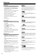
Features Processing • HDMI Audio and Video Processing (Deep Color, x.v.
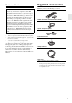
Features—Continued Supplied Accessories Make sure you have the following accessories: THX Ultra2 Plus Before any home theater component can be THX Ultra2 Plus certified, it must pass a rigorous series of quality and performance tests. Only then can a product feature the THX Ultra2 Plus logo, which is your guarantee that the Home Theater products you purchase will give you superb performance for many years to come.
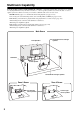
Multiroom Capability You can use three speaker systems with this AV controller—a surround-sound speaker system (up to 7.1 channels) for enjoying DVD movies in your main room, Zone 2: a stereo speaker system in a second room, Zone 3: a stereo speaker system in a third room. And, you can select a different audio source for each room. Main Room: Enjoy up to 7.1-channel surround-sound playback (see page 21–25). You can enjoy the various listening modes, such as Dolby, DTS, and THX (see pages 75–85).
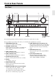
Front & Rear Panels Front Panel 1 9 2 34 5 bk 6 bl 7 Front flap 8 Push here to open the flap The actual front panel has various logos printed on it. They are not shown here for clarity. The page numbers in parentheses show where you can find the main explanation for each item. a ON/STANDBY button (45) Sets the AV controller to On or Standby. b STANDBY indicator (45) Lights up when the AV controller is on Standby and flashes while a signal is being received from the remote controller.
Front & Rear Panels—Continued North American model bm bn bo bp bq br bs bt ck cl cm cn cr cs co cp cq ct Other models dk bt The page numbers in parentheses show where you can find the main explanation for each item. l PHONES jack (66) This 1/4-inch phone jack is for connecting a standard pair of stereo headphones for private listening. v SETUP button This button is used to access the onscreen setup menus that appear on the connected TV.
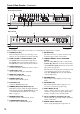
Front & Rear Panels—Continued ct LISTENING MODE [e]/[r] buttons (75) dk POWER switch (45) Select the Onkyo original listening modes. American models do not have this switch. This is the main power switch. When set to OFF, the AV controller is completely shutdown. It must be set to ON to set the AV controller to On or Standby. Display 1 2 5 3 6 7 8 9 4 bk For detailed information, see the pages in parentheses.
Front & Rear Panels—Continued Rear Panel North American model 1 2 3 bt ck cl 4 5 6 78 9 cm cn co cp cq cr cs bk bm bo ct dk dl Other models a u REMOTE CONTROL This u (Remote Interactive) jack can be connected to the u jack on another u-capable Onkyo component for remote and system control. To use u, you must make an analog audio connection (RCA) between the AV controller and the other component, even if they are connected digitally.
Front & Rear Panels—Continued d COMPONENT VIDEO IN 1, 2, and 3 These RCA component video inputs are for connecting components with a component video output, such as a DVD player, DVD recorder, or DVR (digital video recorder). They’re assignable, which means you can assign each one to an input selector to suit your setup. See “Component Video Setup” on page 52. e COMPONENT VIDEO MONITOR OUT 1 This RCA component video output is for connecting a TV or projector with a component video input.
Front & Rear Panels—Continued x TAPE IN/OUT These analog audio input and output jacks are for connecting a recorder with an analog audio input and output, such as a cassette deck, MD recorder, etc. dn PRE OUT: ZONE 2, ZONE 3 y AUX 1 IN A VCR for playback only or other video source can be connected here. There’s S-Video and composite video input jacks for connecting the video signal. do AC OUTLET (North American model only) z GAME/TV IN A game console or TV output can be connected here.
Remote Controller Installing the Batteries 1 To open the battery compartment, press the small hollow and slide open the cover. Aiming the Remote Controller When using the remote controller, point it toward the AV controller’s remote control sensor, as shown below. Remote control sensor STANDBY indicator AV controller 30˚ 2 3 Insert the three supplied batteries (AA/R6) in accordance with the polarity diagram inside the battery compartment. Slide the cover shut.
Remote Controller—Continued About the Remote Controller Modes As well as the AV controller, you can also use the remote controller to control your other AV components. The remote controller has a specific operating mode for use with each type of component. Modes are selected by using the REMOTE MODE buttons. ■ RECEIVER/TAPE Mode In RECEIVER/TAPE mode, you can control the AV controller and an Onkyo cassette recorder connected via u. RECEIVER/TAPE Mode RECEIVER/TAPE mode is used to control the AV controller.
Remote Controller—Continued For detailed information, see the pages in parentheses. t L NIGHT button (102) Turns the Late Night function on or off. a STANDBY button (45) Sets the AV controller to Standby. u AUDIO SEL button (114) Selects the audio input: analog, digital, HDMI, or multichannel. b ON button (45) Turns on the AV controller. c INPUT SELECTOR buttons (64) Used to select the input source. d MACRO buttons (126) Used with the Macro function. e DIMMER button (65) Adjusts the display brightness.
Remote Controller—Continued a STANDBY button Sets the DVD player to Standby. DVD Mode To set the remote controller to DVD mode, press the [DVD] REMOTE MODE button. b ON button Turns on the DVD player. c Number buttons Used to enter title, chapter, and track numbers, and to enter times for locating specific points. 1 2 d TOP MENU button Selects a DVD’s top menu. 3 e Arrow [q]/[w]/[e]/[r] and ENTER buttons Used to navigate menus and select items. f DISC +/– button Selects discs on a DVD changer.
Remote Controller—Continued a STANDBY button Sets the component to Standby. CD/MD/CDR Modes To control an Onkyo CD player, MD recorder, or CD recorder, or a CD or MD player/recorder made by another manufacturer, press the [CD] REMOTE MODE button to select the CD/MD/CDR remote controller mode. In order to control an Onkyo MD recorder or CD recorder, or a component made by another manufacturer, you must first enter the appropriate remote control code (see page 122).
Remote Controller—Continued a STANDBY button Turns off the iPod. DOCK Mode Dock mode is for controlling an Apple iPod in an Onkyo RI Dock. To control an RI Dock, press the [DOCK] REMOTE MODE button to select the DOCK remote controller mode. In order to control an RI Dock, you must first enter the appropriate remote control code (see page 122). When Using an RI Dock: • Connect the RI Dock to the TAPE IN or AUX 1 IN L/R jacks. • Set the RI Dock’s RI MODE switch to HDD or HDD/DOCK.
About Home Theater Enjoying Home Theater Thanks to the AV controller’s superb capabilities, you can enjoy surround sound with a real sense of movement in your own home—just like being in a movie theater or concert hall. With DVDs you can enjoy DTS and Dolby Digital. With analog or digital TV, you can enjoy Dolby Pro Logic IIx, DTS Neo:6, or Onkyo’s original DSP listening modes. You can also enjoy THX Surround EX (THX-certified THX speaker system recommended).
Connecting the AV Controller Connecting Your Speakers The AV controller is designed to be used with a separate multichannel power amplifier. You connect the AV controller’s PRE OUT jacks to the amplifier’s inputs, and connect your speakers to the amplifier’s speakers terminals. Speaker settings such as crossover frequency and distance are set on the AV controller. Speaker Configuration For 7.1-channel surround-sound playback, you need seven speakers and a powered subwoofer.
Connecting the AV Controller—Continued Connecting a Powered Subwoofer Using a suitable cable, connect the AV controller’s SUBWOOFER PRE OUT to the input on your powered subwoofer. If your subwoofer is unpowered and you’re using an external amplifier, connect the SUBWOOFER PRE OUT to the amp’s input. You can also connect a powered subwoofer to the AV controller’s balanced SUBWOOFER PRE OUT XLR jack by using a balanced XLR cable.
Connecting the AV Controller—Continued Connecting a Power Amplifier with XLR Inputs You can connect the AV controller to a multichannel power amplifier with balanced XLR input jacks by using several XLR audio cables. The AV controller’s balanced PRE OUT XLR jacks are wired as shown. See your multichannel power amplifier’s instruction manual for more information on connecting speakers.
Connecting the AV Controller—Continued Bi-amping the Front Speakers The FRONT L/R and SURR BACK L/R outputs can be used with front speakers and surround back speakers, respectively, or bi-amped to provide separate tweeter and woofer feeds for a pair of front speakers that support bi-amping, providing improved bass and treble performance. • When bi-amping is used, the AV controller is able to feed up to 5.1 speakers in the main room.
Connecting the AV Controller—Continued Connecting Antenna 2 This section explains how to connect the supplied indoor FM antenna and AM loop antenna, and how to connect commercially available outdoor FM and AM antennas. Use thumbtacks or something similar to fix the FM antenna into position. The AV controller won’t pick up any radio signals without any antenna connected, so you must connect the antenna to use the tuner. Thumbtacks, etc.
Connecting the AV Controller—Continued ■ Using a TV/FM Antenna Splitter It’s best not to use the same antenna for both FM and TV reception, as this can cause interference problems. If circumstances demand it, use a TV/FM antenna splitter, as shown. ■ Other Models Push Insert wire Release TV/FM antenna splitter To AV controller Once your AV controller is ready for use, you’ll need to tune into an AM radio station and adjust the position of the AM antenna to achieve the best possible reception.
Connecting the AV Controller—Continued AV Connection Color Coding About AV Connections RCA-type AV connections are usually color coded: red, white, and yellow. Use red plugs to connect rightchannel audio inputs and outputs (typically labeled “R”). Use white plugs to connect left-channel audio inputs and outputs (typically labeled “L”). And use yellow plugs to connect composite video inputs and outputs. • Before making any AV connections, read the manuals supplied with your other AV components.
Connecting the AV Controller—Continued Connecting Both Audio & Video By connecting both the audio and video outputs of your DVD player and other AV components to the AV controller, you can switch the audio and video signals simultaneously simply by changing the input source on the AV controller. : Signal Flow Video Video Audio Audio TV, projector, etc. DVD player, etc. On Power On Of f Standby Seven Channel Amplifier RDA-7.
Connecting the AV Controller—Continued ■ “Monitor Out” Setting Set to “Analog” With the “Monitor Out” setting set to “Analog” (see page 46), video input signals flow through the AV controller as shown, with composite video and S-Video sources being upconverted for the component video output. Use this setting if you connect the AV controller’s COMPONENT VIDEO MONITOR OUT 1 or 2 to your TV. Composite video is upconverted to S-Video and S-Video is downconverted to composite video.
Connecting the AV Controller—Continued Connecting a TV or Projector See “Connecting Components with HDMI” on page 37 for HDMI connection information. Step 1: Video Connection Choose a video connection that matches your TV ( A , B , or C ), and then make the connection. Step 2: Audio Connection Choose an audio connection that matches your TV ( a , b , or c ), and then make the connection. • With connection a , you can listen to and record audio from your TV or listen in Zone 2 or Zone 3.
Connecting the AV Controller—Continued Connecting a DVD player Step 1: Video Connection Choose a video connection that matches your DVD player ( A , B , or C ), and then make the connection. If you use connection A , you must connect the AV controller to your TV with the same type of connection. Step 2: Audio Connection Choose an audio connection that matches your DVD player ( a , b , or c ), and then make the connection.
Connecting the AV Controller—Continued Hooking Up the Multichannel Input If your DVD player supports multichannel audio formats such as DVD-Audio and SACD, and it has a multichannel analog audio output, you can connect it to the AV controller’s multichannel input. Use a multichannel analog audio cable, or several normal audio cables, to connect the AV controller’s MULTI CH: FRONT L/R, CENTER, SURR L/R, SURR BACK L/R, and SUBWOOFER jacks to the 7.1-channel analog audio output on your DVD player.
Connecting the AV Controller—Continued Connecting a VCR or DVD Recorder for Playback With this hookup, you can use the tuner in your VCR or DVR to listen to your favorite TV programs via the AV controller, which is useful if your TV has no audio outputs. Hint! Step 1: Video Connection Choose a video connection that matches your VCR or DVD recorder ( A , B , or C ), and then make the connection. If you use connection A , you must connect the AV controller to your TV with the same type of connection.
Connecting the AV Controller—Continued Connecting a VCR or DVD Recorder for Recording Step 1: Video Connection Choose a video connection that matches your VCR or DVD recorder ( A or B ), and then make the connection. The video source to be recorded must be connected to the AV controller via the same type of connection. Step 2: Audio Connection Choose an audio connection that matches your VCR or DVD recorder ( a or b ), and then make the connection.
Connecting the AV Controller—Continued Connecting a Satellite, Cable, Terrestrial Set-top box, or Other Video Source With this hookup, you can use your satellite or cable receiver to listen to your favorite TV programs via the AV controller, which is useful if your TV has no audio outputs. Hint! Step 1: Video Connection Choose a video connection that matches the video source ( A , B , or C ), and then make the connection.
Connecting the AV Controller—Continued Connecting Components with HDMI About HDMI Designed to meet the increased demands of digital TV, HDMI (High Definition Multimedia Interface) is a new digital interface standard for connecting TVs, projectors, DVD players, set-top boxes, and other video components. Until now, several separate video and audio cables have been required to connect AV components.
Connecting the AV Controller—Continued Making HDMI Connections Step 1: Use HDMI cables to connect the AV controller’s HDMI jacks to your HDMI-compatible Blu-ray player/DVD player, TV, projector, and so on. Step 2: Assign each HDMI IN to an input selector. See “Video Input Setup” on page 50. ■ Video Signals Digital video signals received by the HDMI IN jacks are normally output by the HDMI MAIN OUT and SUB OUT for display on your TV.
Connecting the AV Controller—Continued Connecting a Game Console Step 1: Video Connection Choose a video connection that matches your game console ( A , B , or C ), and then make the connection. If you use connection A , you must connect the AV controller to your TV with the same type of connection. Step 2: Audio Connection Choose an audio connection that matches your DVD player ( a , b , or c ), and then make the connection.
Connecting the AV Controller—Continued Connecting a Camcorder or Other Device Step 1: Video Connection Choose a video connection that matches your camcorder ( A or B ), and then make the connection. Step 2: Audio Connection Choose an audio connection that matches your camcorder ( a or b ), and then make the connection. b AUX 2 INPUT DIGITAL a AUX 2 INPUT L AUDIO R AUX 2 INPUT S VIDEO AUX 2 INPUT VIDEO A B VIDEO OUT S VIDEO OUT L AUDIO R OUT OPTICAL OUT Camcorder, etc.
Connecting the AV Controller—Continued Connecting a CD Player or Turntable ■ CD Player or Turntable (MM) with Built-in Phono Preamp Step 1: Choose a connection that matches your CD player ( a , b , or c ). Use connection a for a turntable with a built-in phono preamp.
Connecting the AV Controller—Continued Connecting a Cassette, CDR, MiniDisc, or DAT Recorder Step 1: Choose a connection that matches your recorder ( a , b , c , or d ), and then make the connection. b c a IN COAXIAL IN 2 L (VCR/DVR) R TAPE OPTICAL a IN 2 (CD) L d R OPTICAL TAPE Connect one or the other L COAXIAL OUT OPTICAL OUT OPTICAL IN R AUDIO IN L R AUDIO OUT Cassette, CDR, MD, etc. • With connection a , you can play and record or listen in Zone 2 or Zone 3.
Connecting the AV Controller—Continued Connecting an RI Dock Not all iPod models output video. For information about which iPod models are supported by the RI Dock, see the RI Dock’s instruction manual. ■ If Your iPod Doesn’t Support Video: Connect your RI Dock’s audio output jacks to the AV controller’s AUX 1 IN L/R jacks. (Onkyo DS-A2X hookup shown below.
Connecting the AV Controller—Continued Connecting Onkyo u Components Step 1: Make sure that each Onkyo component is connected to the AV controller with an analog audio cable (RCA). Step 2: Make the necessary u connections (see illustration below). Step 3: If you’re using an MD, CDR, or RI DOCK component, change the Input Display (see page 57).
Turning On the AV Controller • North American model • Other models ON/STANDBY STANDBY indicator ON/STANDBY STANDBY indicator STANDBY ON RECEIVER POWER Turning On and Standby 1 Set the [POWER] switch to the ON position ( ). (Skip this step if you have the North American model.) The AV controller enters Standby mode, and the STANDBY indicator comes on. 2 On the AV controller, press the [ON/STANDBY] button.
First Time Setup This section explains the settings that you need to make before using the AV controller for the very first time. Monitor Setup 1 Press the [HDMI OUT] button. The current setting is displayed. 2 Press the [HDMI OUT] button repeatedly to select: Analog: Select this if your TV is connected to the COMPONENT VIDEO MONITOR OUT 1 or 2, S MONITOR OUT, or V MONITOR OUT. HDMI Main: Select this if your TV is connected to the HDMI OUT MAIN.
First Time Setup—Continued In this Instruction Manual, illustrations from the onscreen menu or explanations referring to the menu will be in the same language as the Instruction Manual. The default Language setting for the onscreen menu is English. If your Instruction Manual is in a language other than English, first follow the instructions below to change the Language.
First Time Setup—Continued ■ Menus for First Time Setup Submenus 1 1. 2. 3. 4. 5. 2 1. Input/Output Assign Monitor Out HDMI Input Component Video Input Digital Audio Input Analog Audio Input MOVE 1 1. 2. 3. 4. 5. 6. p. 49 p. 54 ENTER ENTER RETURN RETURN SETUP EXIT 2. Speaker Setup Speaker Settings Speaker Config Speaker Distance Level Calibration Equalizer Settings THX Audio Setup p. 55 Using the Onscreen Setup Menus Carry out the settings for the AV controller by using the Onscreen Setup Menu.
First Time Setup—Continued Monitor Out Setup 2 Use the Up and Down [q]/[w] buttons to select “1. Input/Output Assign”, and then press [ENTER]. The “Input/Output Assign” menu appears. 1. 2. 3. 4. 5. 3 1 2, 3 2–6 1. Input/Output Assign Monitor Out HDMI Input Component Video Input Digital Audio Input Analog Audio Input Use the Up and Down [q]/[w] buttons to select “1. Monitor Out”, and then press [ENTER]. The “Monitor Out” menu appears. 1–1.
First Time Setup—Continued 5 6 50 Use the Up and Down [q]/[w] buttons to select “Resolution”, and use the Left and Right [e]/[r] buttons to select: Through: Select this to pass video through the AV controller at the same resolution and with no conversion. Auto: Select this to have the AV controller automatically convert video at resolutions not supported by your TV. (Not available when the “Monitor Out” setting is set to “Analog”.) 480p: Select this for 480p output and video conversion as necessary.
First Time Setup—Continued 2 Use the Up and Down [q]/[w] buttons to select “1. Input/Output Assign”, and then press [ENTER]. The “Input/Output Assign” menu appears. 1. 2. 3. 4. 5. 3 1. Input/Output Assign Monitor Out HDMI Input Component Video Input Digital Audio Input Analog Audio Input Use the Up and Down [q]/[w] buttons to select “2. HDMI Input”, and then press [ENTER]. The “HDMI Input” menu appears. 1–2.
First Time Setup—Continued Component Video Setup 2 If you connect a video component to a COMPONENT VIDEO IN, you must assign that input to an input selector. For example, if you connect your DVD player to COMPONENT VIDEO IN 3, you must assign COMPONENT VIDEO IN 3 to the DVD input selector. By default, the DVD input selector is assigned to COMPONENT VIDEO IN 1, and all of the other input selectors are assigned to the “- - -” option.
First Time Setup—Continued Digital Audio Input Setup 4 Use the Up and Down [q]/[w] buttons to select an input selector, and then use the Left and Right [e]/[r] buttons to select: “COAX1”, “COAX2”, “COAX3”, “OPT1”, “OPT2”, or “- - - (analog)”. • When an HDMI IN is assigned to an input selector in “HDMI Input Setup” on page 50, this input assignment is automatically set to the same HDMI IN. And in addition to the usual inputs (e.g., COAX1, COAX2, etc.), you can also select HDMI inputs.
First Time Setup—Continued 3 Analog Audio Input Setup Use the Up and Down [q]/[w] buttons to select “5. Analog Audio Input”, and then press [ENTER]. The “Analog Audio Input” menu appears. 1–5. Analog Audio Input Multich Balance Balance Input VALUE 1 2, 3 Use the Left and Right [e]/[r] buttons to select an input selector. You can assign the multichannel input to the following input selectors: “DVD”, “VCR/DVR”, “CBL/SAT”, “GAME/TV”, “AUX1”, “AUX2”, “TAPE”, “CD”, or “PHONO”.
First Time Setup—Continued Speaker Settings 3 If you change these settings, you must run the automatic speaker setup again (see page 58). Use the Up and Down [q]/[w] buttons to select “1. Speaker Settings”, and then press [ENTER]. The “Speaker Settings” menu appears. 2–1.
First Time Setup—Continued TV Format Setup (not North American models) 4 Use the Up and Down [q]/[w] buttons to select “TV Format”, and then use the Left and Right [e]/[r] buttons to select: Auto: Select this to have the AV controller automatically detect the TV system from the video input signals. NTSC: Select if the TV system in your area is NTSC. PAL: Select if the TV system in your area is PAL. 5 Press the [SETUP] button. Setup closes.
First Time Setup—Continued AM Frequency Step Setup (on some models) 5 Press the [SETUP] button. Setup closes. For AM tuning to work properly, you must specify the AM frequency step used in your area. Note that when this setting is changed, all radio presets are deleted. 1 Press the [RECEIVER] button, followed by the [SETUP] button. The main menu appears onscreen. Note: This procedure can also be performed on the AV controller by using its [SETUP] button, arrow buttons, and [ENTER] button.
First Time Setup—Continued Using the DIGITAL INPUT Button Digital inputs can also be assigned to input selectors by using the [DIGITAL INPUT] button on the AV controller. 1 2, 3 1 58 Press the input selector button for the input selector that you want to assign. 2 Press the [DIGITAL INPUT] button. The current assignment is displayed. 3 Press the [DIGITAL INPUT] button repeatedly to select an option. Available options are the same as for the Digital Input menu. See step 4 on page 53.
First Time Setup—Continued Measurement Positions Using Audyssey MultEQ® XT To create a listening environment in your home theater that all listeners will enjoy, Audysssey MultEQ® takes measurements at up to eight positions within the listening area. 1 ■ 1st measurement position This is the center position of your listening area, or the listening position if there’s only one listener. ■ 2nd–8th measurement positions These are the other listening positions (i.e.
First Time Setup—Continued The onscreen menus shown in this manual may be slightly different from what you see on your TV. 1 2 3 Press [ENTER]. The automatic speaker setup starts. Auto Speaker Setup Turn on the AV controller and the connected TV. On the TV, select the input to which the AV controller is connected. Do not unplug Setup Mic. Please keep quiet. Now measuring. . . 2 Test tones are played through each speaker as Audyssey MultEQ® XT Automatic Speaker Setup runs.
First Time Setup—Continued 6 When prompted, place the setup microphone at the next position, and repeat step 5. 7 After the 3rd or 7th measurement, the following screen appears. Use the Up and Down [q]/[w] buttons to select an option, and then press [ENTER]. Save: Save the calculated settings and exit the automatic speaker setup. Review SP Config: Review the speaker configuration settings (see “Reviewing the Results” on page 63).
First Time Setup—Continued Error Messages Auto Speaker Setup While the automatic speaker setup is in progress, one of the following error messages may appear: Next Cancel ❑ Ambient noise is too high :Yes :--- Auto Speaker Setup :No ! MOVE Retry Cancel :Error Speaker Detect Error ! ENTER ENTER The surround back left speaker has not been detected. Auto Speaker Setup Ambient noise is too high.
First Time Setup—Continued Reviewing the Results Changing the Speaker Settings Manually Use the Up and Down [q]/[w] buttons to select the settings that you want to review, and then press [ENTER]. Auto Speaker Setup Save Review SP Config Review SP Distance Review SP Level Cancel MOVE ENTER ENTER The options are: Review SP Config Review the speaker configuration settings.
Basic Operations Selecting the Input Source 3 1 1 3 1 1 AV controller To select an input source with the remote controller, press its [RECEIVER] REMOTE MODE button, and then use its INPUT SELECTOR buttons. 2 Start playback on the source component. When you select DVD or another video component, on your TV, you’ll need to select the video input that’s connected to the AV controller’s COMPONENT VIDEO MONITOR OUT 1 or COMPONENT VIDEO MONITOR OUT 2/ZONE 2 OUT, HDMI OUT MAIN, HDMI OUT SUB, or MONITOR OUT.
Basic Operations—Continued This section explains functions that can be used with any input source. Adjusting Speaker Levels You can adjust the volume of each speaker while listening to an input source. These temporary adjustments are cancelled when the AV controller is set to Standby. Press [RECEIVER] first DIMMER SLEEP DISPLAY MUTING CH SEL LEVEL – + Use the remote controller’s [CH SEL] button to select each speaker, and use the [LEVEL–] and [LEVEL+] buttons to adjust the volume.
Basic Operations—Continued Using the Sleep Timer With the sleep timer, you can set the AV controller to turn off automatically after a specified period. Adjusting the Bass & Treble You can adjust the bass and treble for the front speakers, except when the Direct, Pure Audio or THX listening mode is selected. Press the [RECEIVER] button, and then press the [SLEEP] button repeatedly to select the required sleep time. The sleep time can be set from 90 to 10 minutes in 10 minute steps.
Listening to the Radio ■ Manual Tuning Mode Listening to AM/FM Stations TUNING MODE 1 Press the [TUNING MODE] button so that the AUTO indicator disappears from the display. 2 Press and hold the TUNING Up or Down [q]/[w] button. The frequency stops changing when you release the button. Press the button repeatedly to change the frequency one step at a time. TUNING TUNER With the built-in tuner, you can enjoy AM and FM radio stations and store your favorite stations as presets for easy selection.
Listening to the Radio—Continued ■ Tuning into Stations by Frequency You can tune into AM and FM stations directly by entering the appropriate frequency. Displaying AM/FM Radio Information DISPLAY Number buttons D.TUN Press the [DISPLAY] button to display the available information. RECEIVER 1 Press the [RECEIVER] button, followed by the [D.TUN] button. The [RECEIVER] button flashes. Band Frequency Preset # Listening mode (Actual display depends on country.
Listening to the Radio—Continued Presetting AM/FM Stations 2, 4 Selecting Presets PRESET 3 You can store a combination of up to 40 of your favorite AM and FM radio stations. 1 Tune into the AM or FM station you want to store as a preset. 2 Press the [MEMORY] button. The preset number flashes. 3 While the preset number is flashing (about 8 seconds), use the PRESET [e]/[r] buttons to select a preset from 1 through 40. 4 Press the [MEMORY] button again to store the station.
Listening to the Radio—Continued Listening to HD Radio™ Stations (North American model only) HD Radio technology brings digital radio to conventional analog AM and FM radio stations, with improved sound quality, better reception, and new data services. HD Radio technology provides CD-quality sound for FM stations and FM-quality sound for AM stations. In addition, FM HD Radio stations can transmit multiple programs on the same frequency by using multicast channels.
Listening to the Radio—Continued Selecting Multicast Channels FM HD Radio stations can transmit multiple programs on the same frequency by using what are called multicast channels. If the current HD Radio station is broadcasting multicast channels, the SPS (secondary program services) indicator lights up. 1 Press [ENTER]. The SPS indicator flashes. Note: Multicast channels 2 through 8 only carry a digital signal, so to select an audio format, you must select multicast channel #1 first.
Listening to the Radio—Continued RDS Program Types (PTY) Using RDS RDS only works in areas where RDS broadcasts are available. When tuned to an RDS station, the RDS indicator appears. RDS indicator Display None NONE News reports NEWS Current affairs AFFAIRS Information INFO Sport SPORT Education EDUCATE Drama DRAMA Culture CULTURE ■ What is RDS? RDS stands for Radio Data System and is a method of transmitting data in FM radio signals.
Listening to the Radio—Continued Displaying Radio Text (RT) 4 To start the search, press [ENTER]. The AV controller searches until it finds a station of the type you specified, at which point it stops briefly before continuing with the search. 5 When a station you want to listen to is found, press [ENTER]. If no stations are found, the message “Not Found” appears. RT/PTY/TP When tuned to an RDS station that’s broadcasting text information, the text can be displayed.
Recording This section explains how to record the input source and how to record audio and video from separate sources. Notes: • The surround sound and DSP listening modes cannot be recorded. • Copy-protected DVDs cannot be recorded. • Sources connected to the analog multichannel input cannot be recorded. • Various restrictions apply to digital recording. Refer to the manuals supplied with your digital recording equipment for more details.
Using the Listening Modes Selecting the Listening Modes Selecting with the Remote Controller For a description of each listening mode, see “About the Listening Modes” on page 82. • The Dolby Digital and DTS listening modes can only be selected if your DVD player is connected to the AV controller with a digital audio connection (coaxial, optical, or HDMI). • The listening modes you can select depends on the format of the input signal. To check the format, see “Displaying Source Information” on page 66.
Using the Listening Modes—Continued Listening Modes Available for Each Source Format Analog and PCM Sources Analog/PCM Source format Media Listening Mode Pure Audio Direct Stereo Mono Multichannel 32–96 kHz*1 CD, TV, radio, ✔ ✔ ✔ ✔ Neo:6 Cinema Neo:6 Music THX Cinema/Music/Games*5 Dolby PLII/Dolby PLIIx Movie + THX Cinema*5 Dolby PLII/Dolby PLIIx Music + THX Music*5 Dolby PLII/Dolby PLIIx Game + THX Games*5 Neo:6 Cinema/Music +THX Cinema/Music*5 Neo:6 + THX Cinema/Music/Game PLII Game + THX Ultra2 Game
Using the Listening Modes—Continued Dolby Digital, and Dolby Digital Plus Sources Source format Multichannel Media Dolby Digital 2ch Mono/Multiplex DVD, DTV, etc.
Using the Listening Modes—Continued DTS Sources ✔: Available Listening Modes Source format DTS, DTS96/24 Multichannel Media 2ch Mono DVD, CD, etc. Listening Mode DVD, CD, etc.
Using the Listening Modes—Continued TrueHD Sources ✔: Available Listening Modes Source format TrueHD Multichannel Media 2ch TrueHD 192kHz Mono/Multiplex Multichannel Blu-ray, HD DVD Listening Mode 2ch Blu-ray, HD DVD Pure Audio ✔ ✔ ✔ ✔ ✔ Direct ✔ ✔ ✔ ✔ ✔ Stereo ✔ ✔ ✔ ✔ ✔ Mono ✔ ✔ ✔ TrueHD ✔ ✔ *2 Neo:6 ✔ Neural THX ✔*4 ✔*3*4 Dolby PLII Movie/ Dolby PLIIx Movie*1 ✔*2 ✔ Dolby PLII Music/ Dolby PLIIx Music*1 ✔*2 ✔ Dolby PLII Game/ Dolby PLIIx Game*1 ✔ ✔*2 Dolby EX
Using the Listening Modes—Continued DTS-HD Sources Source format DTS-HD High Resolution Multi 2ch Mono channel DTS-HD Master Audio Multi 2ch Mono channel ✔: Available Listening Modes DTS-HD Master Audio 192kHz Multi 2ch Mono channel Blu-ray, HD DVD Blu-ray, HD DVD Blu-ray, HD DVD Media Listening Mode Pure Audio Direct Stereo Mono DTS-HD High Resolution DTS-HD Master Audio ✔ ✔ ✔ ✔ ✔ ✔ ✔ ✔ ✔ ✔ ✔ ✔ ✔ ✔ ✔ ✔ ✔ ✔ ✔ ✔ ✔ ✔ ✔ ✔ ✔ ✔*2 Neural THX ✔*2 ✔*4 ✔*3*4 ✔*4 ✔*3*4 Dolby PLII Movie/ Dol
Using the Listening Modes—Continued DTS Express and DSD Sources ✔: Available Listening Modes DSD*1 DTS Express Source format Multichannel Media Listening Mode Pure Audio Direct Stereo Mono DTS Express DSD Neo:6 2ch Mono Multichannel (3/2.
Using the Listening Modes—Continued About the Listening Modes The AV controller’s listening modes can transform your listening room into a movie theater or concert hall, with high fidelity and stunning surround sound. The LISTENING MODE button illustration shows that listening modes can be selected.
Using the Listening Modes—Continued Dolby TrueHD Designed to take full advantage of the additional storage space offered by the new Blu-ray and HD DVD disc formats, this new Dolby format offers up to 7.1 discrete channels of digital audio with 48/96 kHz, up to 5.1-channels with 192 kHz sampling rate. For the signals supported by the AV controller, see page 79. 5.1-channel source + Dolby PLIIx Music These modes use the Dolby Pro Logic IIx Music mode to expand 5.1-channel sources for 6.1/7.1-channel playback.
Using the Listening Modes—Continued Neural THX 5.1/7.1 Neural-THX Surround employs psychoacoustic frequency domain processing, which allows delivery of a more detailed sound stage, with superior channel separation and localization of audio elements. The Neural THX 5.1 and Neural THX 7.1 modes can expand any 2-channel stereo source for 5.1- or 7.1-channel playback, respectively. Use them with CD, radio, cassette, TV, VHS, DVD, and other 2-channel stereo sources, including video games.
Using the Listening Modes—Continued Onkyo Original DSP Modes Mono Movie This mode is suitable for old movies and other mono sources. The center speaker outputs the sound as it is, while reverb is applied to the sound output by the other speakers, giving presence to even mono material. Orchestra Suitable for classical or operatic music, this mode emphasizes the surround channels in order to widen the stereo image, and simulates the natural reverberation of a large hall.
Advanced Setup The onscreen setup menus appear on the connected TV and provide a convenient way to change the AV controller’s various settings. Settings are organized into eight categories on the main menu, most containing a submenu. The onscreen menus shown in this manual may be slightly different from what you see on your TV. MENU 1. Input/Output Assign 2. Speaker Setup 3. Audio Adjust 4. Source Setup 5. Listening Mode Preset 6. Miscellaneous 7. Hardware Setup 8.
Advanced Setup—Continued Monitor Out Setup 3 Use the Up and Down [q]/[w] buttons to select an item, and then press [ENTER]. The screen for that item appears. 4 Use the Up and Down [q]/[w] buttons to select an item, and use the Left and Right [e]/[r] buttons to change it. The items are explained below. 5 When you’ve finished, press the [SETUP] button. Setup closes. This section explains items on the “Input/Output Assign” menu.
Advanced Setup—Continued Monitor Out Resolution You can specify the output resolution for the HDMI outputs and have the AV controller upconvert the picture resolution as necessary to match the resolution supported by your TV. Through: Select this to pass video through the AV controller at the same resolution and with no conversion (default). Auto: Select this to have the AV controller automatically convert video at resolutions not supported by your TV.
Advanced Setup—Continued Speaker Setup 1 Press the [RECEIVER] REMOTE MODE button. 2 Press the [SETUP] button. The main menu appears onscreen. 3 Use the Up and Down [q]/[w] buttons to select “2. Speaker Setup”, and then press [ENTER]. The “Speaker Setup” menu appears. This section explains items on the “Speaker Setup” menu. Some of the speaker settings are set automatically by the Automatic Speaker Setup function (see page 58). 1 3-12 2, 13 1. 2. 3. 4. 5. 6. Speaker Settings 2.
Advanced Setup—Continued 5 6 Use the Up and Down [q]/[w] buttons to select “Subwoofer”, and then use the Left and Right [e]/[r] buttons to select: Yes: Select if a subwoofer is connected. No: Select if no subwoofer is connected. Use the Up and Down [q]/[w] buttons to select “Front”, and then use the Left and Right [e]/[r] buttons to select a crossover frequency. Note: Fixed at “Full Band” if “Subwoofer” (step 5) is set to “No”.
Advanced Setup—Continued Low-Pass Filter for the LFE Channel Double Bass This setting is not set automatically by the Automatic Speaker Setup function (see page 58). This setting is not set automatically by the Automatic Speaker Setup function (see page 58). With this setting, you can specify the cutoff frequency of the LFE channel’s low-pass filter (LPF), which can be used to filter out unwanted hum. The LPF only applies to sources that use the LFE channel.
Advanced Setup—Continued Speaker Distance 5 These settings are set automatically by the Automatic Speaker Setup function (see page 58). With the “Speaker Distance” settings, you can specify the distance from each speaker to the listening position. Use the Up and Down [q]/[w] buttons to select “3. Speaker Distance”, and then press [ENTER]. The “Speaker Distance” screen appears. 2–3. Speaker Distance Unit feet Left 12.0ft Center 12.0ft Right 12.0ft SurrRight 12.0ft SurrBack R 12.0ft SurrBack L 12.
Advanced Setup—Continued 7 Use the Up and Down [q]/[w] buttons to select a speaker, and use the Left and Right [e]/[r] buttons to specify the distance. Specify the distance from the speaker to your listening position. Notes: • The “Center” distance cannot be set if the “Center” is set to “None” (page 89). • The “SurrRight” and “SurrLeft” distances cannot be set if the “Surround” is set to “None” (page 89).
Advanced Setup—Continued 3 Use the Up and Down [q]/[w] buttons to select “2. Speaker Setup”, and then press [ENTER]. The “Speaker Setup” menu appears. 1. 2. 3. 4. 5. 6. 2. Speaker Setup Speaker Settings Speaker Config Speaker Distance Level Calibration Equalizer Settings THX Audio Setup MOVE 4 2–4. Level Calibration Left -12.0dB Center -12.0dB Right -12.0dB -12.0dB SurrRight SurrBack R -12.0dB SurrBack L -12.0dB SurrLeft -12.0dB Subwoofer -15.
Advanced Setup—Continued Equalizer Settings 2–5. Equalizer Settings 630Hz 1000Hz 1600Hz 2500Hz 4000Hz 6300Hz 10000Hz 16000Hz These settings are set automatically by the Automatic Speaker Setup function (see page 58). With the Equalizer settings, you can adjust the tone of speakers individually with a 7-band equalizer. The volume of each speaker can be set on page 93. 1 2-7 Press the [RECEIVER] REMOTE MODE button, followed by the [SETUP] button. The main menu appears onscreen.
Advanced Setup—Continued ■ MultEQ XT Audyssey MultEQ XT correction is active (see page 58). 7 Use the Up and Down [q]/[w] buttons to select “Channel”, and then use the Left and Right [e]/[r] buttons to select another speaker. Repeat steps 6 and 7 for each speaker. 8 Press the [SETUP] button. The setup menu closes. ■ Dynamic EQ “Audyssey MultEQ XT” and “Dynamic EQ” becomes active (see page 58).
Advanced Setup—Continued THX Audio Setup 4 These settings are not set automatically by the Automatic Speaker Setup function (see page 58). With the “SurrBack Sp Spacing” setting, you can specify the distance between your surround back speakers. If you’re using a THX-certified subwoofer, set the “THX Subwoofer” setting to “Yes”. You can then apply THX’s Boundary Gain Compensation (BGC) to compensate the perceived exaggeration of low frequencies for listeners sitting very close to a room boundary (i.e.
Advanced Setup—Continued 7 8 9 Use the Up and Down [q]/[w] buttons to select “Loudness Plus”, and use the Left and Right [e]/[r] buttons to select: Off: Select this to turn off Loudness Plus. On: Select this to turn on Loudness Plus (default). When “Loudness Plus” is set to “Off”, the “Preserve THX settings” selection will appear under “Loudness Plus” (Step 8).
Advanced Setup—Continued 5 When you’ve finished, press the [SETUP] button. The setup menu closes. Note: This procedure can also be performed on the AV controller by using its [SETUP] button, arrow buttons, and [ENTER] button. Multiplex/Mono Settings Multiplex ■ Input Ch(Mux) This setting determines which channel of a stereo multiplex source is output. Use it to select audio channels or languages with multiplex sources, multilingual TV broadcasts, and so on. Main: The main channel is output (default).
Advanced Setup—Continued ■ Dimension With this setting, you can move the sound field forward or backward when using the Dolby Pro Logic IIx Music listening mode. It can be adjusted from –3 to +3. The default value is 0. Lower settings move the sound field forward. Higher settings move it backward. If the stereo image feels too wide, or there’s too much surround sound, move the sound field forward to improve the balance.
Advanced Setup—Continued Optimizer The Music Optimizer function enhances the sound quality of compressed music files. Use it with music files that use “lossy” compression, such as MP3. Off: Music Optimizer off (default). On: Music Optimizer on. RECEIVER Note: The Music Optimizer function only works with PCM digital audio input signals with a sampling rate below 48 kHz and analog audio input signals. The Music Optimizer is disabled when the Pure Audio or Direct listening mode is selected.
Advanced Setup—Continued Using the Late Night Function With the Late Night function, you can reduce the dynamic range of Dolby Digital material so that you can still hear quiet parts even when listening at low volume levels—ideal for watching movies late at night when you don’t want to disturb anyone. Source Setup This section explains items on the “Source Setup” menu. Items can be set individually for each input selector.
Advanced Setup—Continued 5 Use the Up and Down [q]/[w] buttons to select an option, and use the Left and Right [e]/[r] buttons to change it. The “Source Setup” menu items are explained below. 6 When you’ve finished, press the [SETUP] button. Setup closes. Name Edit You can enter a custom name for each individual input selector and radio preset for easy identification. When entered, the custom name will appear on the display. The custom name is edited using the character input screen. 1.
Advanced Setup—Continued Picture Adjust Zoom: The new “4-4. Picture Adjust” item has been added to the “1. Input/Output Assign” menu. This menu and its settings can be accessed just like the other menus. The settings are explained below. ■ Game Mode If video signal delay occurs during play on a video component, such as a Game console, connected to the AV controller, select “Game Mode” on the input selector connected to the component and set it to “On”.
Advanced Setup—Continued Resolution You can specify the output resolution for the HDMI outputs and have the AV controller upconvert the picture resolution as necessary to match the resolution supported by your TV. Available only when Source has been selected under the “1-1. Monitor Out” setting. Through: Select this to pass video through the AV controller at the same resolution and with no conversion (default).
Advanced Setup—Continued R Brightness: With this setting you can adjust the picture red brightness. Can be adjusted from –50 to +50 in steps of 1 (default is 0). “–50” is the darkest. “+50” is the brightest. R Contrast: With this setting you can adjust red Contrast. Can be adjusted from –50 to +50 in steps of 1 (default is 0). “–50” is the least. “+50” is the greatest. G Brightness: With this setting you can adjust the picture green brightness. Can be adjusted from –50 to +50 in steps of 1 (default is 0).
Advanced Setup—Continued Listening Mode Presets 4 On the “Listening Mode Preset” menu, you can specify a default listening mode for each of the audio formats supported by each input selector. The AV controller will then select the listening mode automatically depending on the format of the input signal. You can still select the other listening modes, although the default listening mode will be used the next time you turn on the AV controller.
Advanced Setup—Continued Miscellaneous Setup 4 Use the Up and Down [q]/[w] buttons to select an item, and use the Left and Right [e]/[r] buttons to change it. The items are explained below. 5 When you’ve finished, press the [SETUP] button. Setup closes. This section explains items on the “Miscellaneous” menu. 1 3-12 2, 13 1 Press the [RECEIVER] REMOTE MODE button, followed by the [SETUP] button. The main menu appears onscreen.
Advanced Setup—Continued ■ Power On Volume This setting determines what the volume will be each time the AV controller is turned on. When the “Volume Display” preference is set to “Absolute”, the range is “Last”, “Min”, 1 to “Max”. When it’s set to “Relative”, the range is “Last”, –∞ dB, –81 dB to +18 dB. To use the same volume level as when the AV controller was last turned off, select “Last”. Note: The “Power On Volume” setting cannot be set higher than the “Maximum Volume” setting.
Advanced Setup—Continued Hardware Setup 4 Use the Up and Down [q]/[w] buttons to select an item, and use the Left and Right [e]/[r] buttons to change it. The items are explained below. 5 When you’ve finished, press the [SETUP] button. Setup closes. This section explains items on the Hardware menu. Remote indicator INPUT Number buttons RECEIVER ENTER Note: This procedure can also be performed on the AV controller by using its [SETUP] button, arrow buttons, and [ENTER] button.
Advanced Setup—Continued Tuner ■ AM Freq Step (on some models) See “AM Frequency Step Setup (on some models)” on page 57. ■ Satellite Radio (on North American model) If you connect an XM Satellite Radio antenna or SIRIUS Satellite Radio antenna to the AV controller (both sold separately), set this setting to XM or SIRIUS respectively. If you connect both types of antenna, select XM/SIRIUS. Otherwise, select None. See the separate Satellite Radio Guide for more information.
Advanced Setup—Continued Power Control To link the power functions of -compatible components connected via HDMI, select “Enable”. Disable: Power Control disabled. Enable: Power Control enabled. Notes: • The “Power Control” setting can be set only when the above “Control” setting is set to “Enable”. • HDMI power control only works with -compatible components that support it and may not work properly with some components due to their settings or compatibility.
Advanced Setup—Continued 3 Use the Up and Down [q]/[w] buttons to select “6. Network”, and then press [ENTER]. The “Network” screen appears. 7-6. Network xx : xx : xx : xx : xx : xx MAC Address Enable Control xxxxx Port Control This setting enables or disables control over the network. Enable: Control over the network enabled. Disable: Control over the network disabled. Port This is the network port used for control over the network.
Advanced Setup—Continued Selecting Audio Inputs Specifying the Digital Signal Format 1 2 AUDIO SEL If you connect a component to more than one audio input, such as a DVD player connected to analog, digital, multichannel, and HDMI inputs, you can use the [AUDIO SEL] button to select which audio input you want to use to listen to that component. Press the [AUDIO SEL] button repeatedly to select an audio input: HDMI > Auto > Multich > Analog.
Zone 2 and Zone 3 In addition to your main listening room, you can also enjoy playback in two other rooms, or as we call them, Zone 2 and Zone 3. And, you can select a different source for each room. Connecting Zone 2 Zone 2 speakers must be connected to an amp in Zone 2. Connecting Your Zone 2 Speakers You can enjoy 2-channel stereo playback in Zone 2 and a different source to those selected for your main room and Zone 3.
Zone 2 and Zone 3—Continued Connecting Zone 3 Zone 3 speakers must be connected to an amp in Zone 3. Connecting Your Zone 3 Speakers You can enjoy 2-channel stereo playback in Zone 3 and a different source to those selected for your main room and Zone 2. Hookup • Use an RCA audio cable to connect the AV controller’s ZONE 3 PRE OUT L/R jacks to an analog audio input on your Zone 3 amp.
Zone 2 and Zone 3—Continued Zone 2/Zone 3 Out Settings 5 Press the [SETUP] button. Setup closes. If you’ve connected your Zone 2 or Zone 3 speakers to an amp with no volume control, set the “Zone2 Out” or “Zone3 Out” setting, respectively, to “Variable” so that you can set the zone’s volume, balance, and tone on the AV controller. 1 2 Press the [RECEIVER] REMOTE MODE button, followed by the [SETUP] button. The main menu appears onscreen.
Zone 2 and Zone 3—Continued Selecting an Input Source for Zones 1 On the remote controller, press the [ZONE2] or [ZONE3] REMOTE MODE button. Remote controller Turning Off Zones 1 Remote controller On the AV controller, press the [ZONE 2] or [ZONE 3] button. AV controller On the AV controller, press the [ZONE 2] or [ZONE 3] button. AV controller The ZONE 2 or ZONE 3 indicator flashes, and the input selector currently selected for the zone appears on the display.
Zone 2 and Zone 3—Continued Adjusting the Volume of Zones 1 Remote controller On the remote controller, press the [ZONE2] or [ZONE3] REMOTE MODE button. Adjusting the Tone and Balance of Zones 1 AV controller On the AV controller, press the [ZONE 2] or [ZONE 3] button. On the AV controller, press the [ZONE 2] or [ZONE 3] button. AV controller 2 Remote controller The ZONE 2 or ZONE 3 indicator flashes. 2 Press the AV controller’s [TONE] button repeatedly to select “Bass” “Treble” or “Balance”.
Zone 2 and Zone 3—Continued Using the 12V Triggers 3 The 12V triggers A, B, and C can be used to turn on 12V trigger-capable components automatically when they are selected as the input source. The triggers can be set so that they activate when a connected component is selected as the input source for the main room, Zone 2, Zone 3, or any combination of rooms. When triggered, the output from a 12V TRIGGER OUT goes high (+12 volts, 100 milliamperes max).
Zone 2 and Zone 3—Continued Using the Remote Controller in Zone 2/3 and Multiroom Control Kits To control the AV controller with the remote controller while you’re in Zone 2 or Zone 3, you’ll need a commercially available multiroom remote control kit for each zone. • Multiroom kits are made by Niles and Xantech. These kits can also be used when there isn’t a clear line of sight to the AV controller’s remote sensor, such as when it’s installed inside a cabinet.
Controlling Other Components You can control your other components, including those made by other manufacturers, with the remote controller. This section explains how to: • Enter the remote control code for a component that you want to control: DVD, TV, VCR, etc. • Learn commands directly from another component’s remote controller (see page 125). • Program the MACRO buttons to perform a sequence of up to eight remote control actions (see page 126).
Controlling Other Components—Continued Remote Control Codes for Onkyo Components Connected via u Onkyo components that are connected via u are controlled by pointing the remote controller at the AV controller, not the component. This allows you to control components that are out of view, in a rack, for example.
Controlling Other Components—Continued To control another component, point the remote controller at it and use the buttons explained below. (You must select the appropriate remote controller mode with the REMOTE MODE buttons first.) With some components, certain buttons may not work as expected, and some may not work at all.
Controlling Other Components—Continued Learning Commands If the command is learned successfully, the Remote indicator flashes twice.
Controlling Other Components—Continued Using Macros You can program the remote controller’s MACRO buttons to perform a sequence of remote control actions. Example: To play a CD you typically need to perform the following actions: 1. Press the [RECEIVER] REMOTE MODE button to select the Receiver remote controller mode. 2. Press the [ON] button to turn on the AV controller. 3. Press the [CD] INPUT SELECTOR button to select the CD input source. 4.
Troubleshooting If you have any trouble using the AV controller, look for a solution in this section. If you can’t resolve the issue yourself, contact your Onkyo dealer. If you can’t resolve the issue yourself, try resetting the AV controller before contacting your Onkyo dealer. To reset the AV controller to its factory defaults, turn it on and, while holding down the [VCR/DVR] button, press the [ON/STANDBY] button. “Clear” will appear on the display and the AV controller will enter Standby mode.
Troubleshooting—Continued The Zone 2/3 speakers produce no sound • The Zone 2/3 speakers only output sources that are connected to an analog input. Check to see if the source component is connected to an analog input. There’s no sound with a certain signal format • Check the digital audio output setting on the source component. On some game consoles, such as those that can play DVDs, the default setting is off.
Troubleshooting—Continued There’s no picture from a source connected to an HDMI IN • When the “Monitor Out” setting is set to “Analog”, and the “Resolution” setting is set to anything other than “Through” (see page 49), no video is output by the HDMI OUT. • If the message “Resolution Error” appears on the AV controller’s display, this indicates that your TV does not support the current video resolution and you need to select another resolution on your DVD player.
Troubleshooting—Continued Recording Can’t record • On your recorder, make sure the correct input is selected. • To prevent signal loops and damage to the AV controller, input signals are not fed through to outputs with the same name (e.g., TAPE IN to TAPE OUT or VCR/DVR IN to VCR/DVR OUT). • When the Pure Audio listening mode is selected, video recording is not possible because no video signals are output. Select another listening mode.
Video Resolution Chart The following tables show how video signals at different resolutions are output by the AV controller.
Specifications Amplifier Section General THD (Total Harmonic Distortion) Input Sensitivity and Impedance Power Supply North American: European and Asian: Power Consumption North American: European and Asian: Dimensions (W × H × D) Output Level and Impedance Phono Overload Frequency Response Tone Control Signal to Noise Ratio 0.05% (Power Rated) 200 mV/ 47 kΩ (LINE) 2.5 mV/47 kΩ (PHONO MM) 200 mV/ 470 Ω (REC OUT) 70 mV (MM 1 kHz, 0.
Memo 133
Sales & Product Planning Div. : 2-1, Nisshin-cho, Neyagawa-shi, OSAKA 572-8540, JAPAN Tel: 072-831-8023 Fax: 072-831-8163 ONKYO U.S.A. CORPORATION 18 Park Way, Upper Saddle River, N.J. 07458, U.S.A. Tel: 201-785-2600 Fax: 201-785-2650 http://www.us.onkyo.com/ ONKYO EUROPE ELECTRONICS GmbH Liegnitzerstrasse 6, 82194 Groebenzell, GERMANY Tel: +49-8142-4401-0 Fax: +49-8142-4401-555 http://www.eu.onkyo.