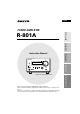
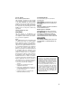
English TUNER AMPLIFIER Before using R-801A Connections TUNER AMPLIFIER VOLUME PHONES DISPLAY MEMORY FM MODE CLEAR INPUT TUNING ACOUSTIC PRESENCE R- 8 01A Operation STANDBY STANDBY / ON Preparations Instruction Manual European models front panel shown. Other Information Thank you for purchasing the ONKYO R-801A Tuner Amplifier. Please read this manual thoroughly before making any connection or turning on the power.
WARNING: TO REDUCE THE RISK OF FIRE OR ELECTRIC SHOCK, DO NOT EXPOSE THIS APPLIANCE TO RAIN OR MOISTURE. CAUTION: TO REDUCE THE RISK OF ELECTRIC SHOCK, DO NOT REMOVE COVER (OR BACK). NO USER-SERVICEABLE PARTS INSIDE. REFER SERVICING TO QUALIFIED SERVICE PERSONNEL.
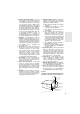
14. Outdoor Antenna Grounding – If an outside antenna or cable system is connected to the appliance, be sure the antenna or cable system is grounded so as to provide some protection against voltage surges and built-up static charges.
Precautions 1. Recording Copyright Recording of copyrighted material for other than personal use is illegal without permission of the copyright holder. 2. AC Fuse The fuse is located inside the chassis and is not user-serviceable. If power does not come on, contact your Onkyo authorized service station. 3. Care From time to time you should wipe the front and rear panels and the cabinet with a soft cloth.
For U.S. model For Canadian model Note to CATV system installer: This reminder is provided to call the CATV system installer’s attention to Article 820-40 of the NEC, ANSI/NFPA 70, which provides guidelines for proper grounding and, in particular, specifies that the cable ground shall be connected to the grounding system of the building, as close to the point of cable entry as practical.
Main Features • A compact, discrete component with 155mm (6-1/8") wide • 24 Watts per channel into 4 ohms DIN • Low impedance drive discrete output stage • Accoustic Presence • RDS (Radio Data System) PS only (European model) • FM/AM random 30 Stations Preset Tuning • Timer Play (Weekday,Weekend),Sleep & Timer Rec • Automatic Scan Tuning (FM only) • FM TUNED Indicator • Audio Muting (operable via remote control) • Battery-free Backup System to Protect Memory Contents • Motor driven Volume control • Head ph
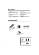
Table of contents Before using Supplied accessories ............................................................................................................ 6 Connections Connecting to the ONKYO Separate Collection Series components ............................... 8 Connecting to components other than the Separate Collection Series ........................ 13 Connecting speaker systems............................................................................................. 16 Antenna connections ..
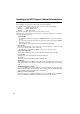
Connecting to the ONKYO Separate Collection Series components This section introduces you to the other Separate Collection Series system components and their convenient system functions, followed by connecting instructions. The following Separate Collection Series components are commercially available: • C-701A .............. Compact Disc (CD) Player • MD-101A ........... Minidisc (MD) Recorder • CDR-201A ......... Audio CD Recorder Note that the available components may vary according to the area.
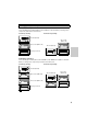
Arranging the system components Combination example 1 Select the CD player C-701A and CD recorder in addition to this unit. When you arrange these components, stack them as shown below. Vertical way stacking Horizontal way stacking This unit (R-801A) CD recorder (CDR-201A) CD recorder (CDR-201A) This unit (R-801A) CD player (C-701A) CD player (C-701A) Combination example 2 Select the CD player C-701A, CD recorder and MD recorder MD-101A in addition to this unit.
Connecting to the ONKYO Separate Collection Series components Connecting to the audio connector Before connecting • Do not connect the unit’s AC power cord (mains lead) to a wall outlet (the mains) until you have completed all the other connections, including and AC OUTLET connections on page 12 and “Connecting speaker systems” on page 16. • On each pair of connectors, a red connector (marked R) corresponds to the right channel, and a white connector (marked L) to the left channel.
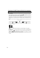
Note: To connect both the MD recorder MD-101A and CD player C-701A to the unit: Connect the MD recorder to the unit following the “Connection for combination example.” The European model is shown in the following illustrations. Connections for combination example CD/DVD OUT IN TAPE IN CD/DVD ANTENNA L IN OUT TAPE IN SUBWOOFER PRE OUT L REMOTE CONTROL AM OUT R FM 75 OUT MD IN OUT CDR/PC R L R L R MD IN OUT CDR/PC SPEAKERS IN L CAUTION: R SPEAKER IMPEDANCE 4 OHMS MIN.
Connecting to the ONKYO Separate Collection Series components Connecting the connectors and AC OUTLETS Before connecting • The hookups on page 11 is needed in addition to the (for remote control operations) and AC OUTLET (for power supply to each component) hookups on this page. • Each component has two connectors. There is no difference between those connectors. The components may be connected in any order.
Connecting to components other than the Separate Collection Series Connecting audio/video equipment to audio connectors Before connecting • Do not connect the AC power cord (mains lead) to the wall outlet (the mains) until you have completed all the other connections including the sound processor connections on the next page, the connections on page 15, and the speaker connections on page 16.
Connecting to components other than the Separate Collection Series Connecting a subwoofer Before connecting • If your subwoofer isn’t equipped with an amplifier, connect a separate amplifier to the unit first, then connect the subwoofer to that amplifier. • The SUBWOOFER PRE OUT connector supplies the left and right mixed monaural signals to the subwoofer.
Connecting the remote control cables If your other components are made by ONKYO and those components are equipped with connectors, you can control the -connected components with the supplied remote controller. Before connecting • The unit must be connected in the system hookups for control operations. • Each component has two connectors. There is no difference between these connectors. • The components may be connected in any order.
Connecting speaker systems Connecting left and right speakers Before connecting • The load impedance of each speaker must be at least 4 ohms. • Do not use unnecessarily long or extremely thin speaker cords. Otherwise, the DC resistance of the speaker cords may become too high, lowering the damping factor and causing the sound quality to deteriorate. • Do not connect the speaker cord to the L and R connectors at the same time and do not connect two or more speakers to the same speaker connectors.
Antenna connections Connecting the AM antenna Assembling the AM loop antenna Assemble the loop antenna as shown in the illustration. Insert into the hole. Connecting the antenna cable 1. Press down the lever. 2. Insert the wire into the hole. 3. Release the lever to replace it. Connecting the AM loop antenna The AM loop antenna is for indoor use only. Set it in the direction and position where you receive the clearest sound.
Antenna connections Connecting the FM antenna FM indoor antenna The supplied FM antenna is for indoor use only. Move the antenna in various directions until the clearest signal is received. Fix it with push pins or similar implements in the position that will cause the least amount of distortion. Other models U.S and Canadian models ANTENNA Remove the insulation at the tip of the cable, and insert the cable securely, fully to the end of the exposed tip.
Connecting the antenna cable to the 75/300 ohm antenna adapter (NonEuropean models) Connecting the 300 ohm ribbon wire: Loosen the screws and wrap the wire around these screws. Then tighten the screws with a screwdriver. Outdoor antenna Indoor antenna 300 ohms ribbon wire Connecting the coaxial cable: 1. With your fingernail or a small screwdriver, press the stoppers outward and remove the cover. 2. Remove the transformer wire A from slit B and insert it into slit C. Slit B Wire A Slit C 3.
Preparing the remote controller Installing the remote controller batteries 1 Remove the battery compartment cover by pressing and sliding it away from the remote controller unit. remote controller doesn’t operate smoothly, replace both the batteries at the same time. • The life of the batteries supplied is about six months but this will vary depending on usage. Using the remote controller Point the remote controller toward the remote control sensor.
Connecting the AC power cord (mains lead) TUNER AMPLIFIER VOLUME STANDBY/ON indicator STANDBY STANDBY / ON PHONES DISPLAY MEMORY FM MODE CLEAR INPUT TUNING ACOUSTIC PRESENCE R- 8 01A .
Setting the Clock The ”ACCUCLOCK“ features an automatic clock adjusting function automatically sets the clock time by means of RDS broadcast signals. • The “ACCUCLOCK” feature is available only on the European model, and only in areas where RDS broadcasts are available. • Adjust the clock as explained in “Setting the clock manually” on page 24 if you are using U.S. or Canadian models or if you are using the unit in the area where RDS broadcasts are unavailable.
STANDBY/ ON ACOUSTIC PRESENCE CDR/PC TAPE CD/ DVD MD INPUT SELECTOR FM AM VOLUME UP TAPE REW TAPE FF MUTING DOWN SLEEP TIMER CLOCK TIMER MODE TAPE REPEAT CD/DVD CLEAR MD CDR/PC SCROLL 1 2 3 4 5 6 7 8 9 10/0 --/--- Confirming/changing the RDS station used by ACCUCLOCK If you wish to know which RDS station has been used to set the clock by ACCUCLOCK, or to use a different RDS station signal to set the clock, follow the steps below: , ENTER ENTER 2 If “AUTO” appears on the
Setting the Clock STANDBY/ON STANDBY/ ON ACOUSTIC PRESENCE CDR/PC TAPE CD/ DVD MD INPUT SELECTOR FM AM VOLUME UP TAPE REW TAPE FF MUTING DOWN SLEEP TIMER CLOCK TIMER MODE TAPE REPEAT CD/DVD ENTER MD CLEAR CDR/PC SCROLL 3 4 5 6 7 8 9 10/0 --/--- 1 , ENTER 2 Setting the clock manually • The explanation in this section assumes that the unit has been powered on (set to “Stand-by On”). This section explains how to set the clock using the 24-hour display.
STANDBY/ ON ACOUSTIC PRESENCE CDR/PC TAPE CD/ DVD MD INPUT SELECTOR FM AM VOLUME UP TAPE REW TAPE FF , MUTING DOWN CLOCK TIMER SLEEP REPEAT CD/DVD CLEAR MD SCROLL CDR/PC or 4 8 5 6 7 9 10/0 --/--- ENTER 3 4 6 7 8 9 10/0 --/--- the or button or the number buttons to set the desired time. 3 ENTER 5 4 Use 2 TIMER TAPE 1 1 CLOCK MODE Entering the time value using the number buttons on the remote controller: To set 9:38 am, press 10/0, 9, 3, 8, then ENTER.
Setting the Clock STANDBY/ ON ACOUSTIC PRESENCE CDR/PC TAPE CD/ DVD MD INPUT SELECTOR FM AM VOLUME UP TAPE REW TAPE FF MUTING DOWN CLOCK SLEEP CLOCK TIMER MODE TAPE REPEAT CD/DVD CLEAR MD ENTER CDR/PC SCROLL 1 2 3 4 5 6 7 8 9 10/0 --/--- Clock Call function While the unit is in Standby/Off mode: CLOCK 1 Press the CLOCK button to display the time, press again to cancel the time display. CLOCK Note If the time has not been set, “ADJUST” will flash on the display.
Choosing the required source INPUT VOLUME STANDBY/ ON ACOUSTIC PRESENCE CDR/PC TAPE CD/ DVD MD INPUT SELECTOR INPUT SELECTOR TUNER AMPLIFIER FM AM VOLUME VOLUME UP TAPE REW TAPE FF MUTING VOLUME UPπ/DOWN† DOWN SLEEP STANDBY STANDBY / ON DISPLAY MEMORY FM MODE INPUT CLOCK TAPE REPEAT CD/DVD MD CLEAR ACOUSTIC PRESENCE R- 8 01A 1 Press the INPUT button repeatedly or the INPUT SELECTOR buttons on the remote controller to select the source you wish to listen to lights.
Adjusting the sound STANDBY/ ON ACOUSTIC PRESENCE CDR/PC TAPE CD/ DVD MD TUNER AMPLIFIER INPUT SELECTOR FM AM VOLUME VOLUME UP TAPE REW TAPE FF MUTING DOWN SLEEP STANDBY STANDBY / ON DISPLAY MEMORY FM MODE INPUT ACOUSTIC PRESENCE R- 8 01A ACOUSTIC PRESENCE Acoustic Presence adds realness to music through the use of exclusive Onkyo circuitry. Presence settings 1, 2, 3 and 4 are ideally suited for use with compact speakers.
Muting/Listening with the headphones STANDBY/ ON ACOUSTIC PRESENCE CDR/PC TAPE CD/ DVD MD TUNER AMPLIFIER VOLUME INPUT SELECTOR FM AM VOLUME UP TAPE REW MUTING TAPE FF MUTING DOWN SLEEP CLOCK TIMER MODE TAPE REPEAT CD/DVD CLEAR MD SCROLL CDR/PC ENTER VOLUME UPπ/DOWN† STANDBY STANDBY / ON DISPLAY PHONES MEMORY FM MODE CLEAR INPUT TUNING ACOUSTIC PRESENCE R- 8 01A 1 2 3 4 5 6 7 8 9 10/0 --/--- Muting the sound Press the MUTING button on the remote controller to
Recording INPUT STANDBY/ ON ACOUSTIC PRESENCE CDR/PC TAPE CD/ DVD MD INPUT SELECTOR FM AM TUNER AMPLIFIER VOLUME VOLUME UP TAPE REW TAPE FF MUTING INPUT SELECTOR DOWN SLEEP CLOCK TIMER MODE TAPE REPEAT CD/DVD CLEAR MD ENTER STANDBY STANDBY / ON PHONES DISPLAY MEMORY INPUT FM MODE TUNING CLEAR CDR/PC SCROLL ACOUSTIC PRESENCE R- 8 01A Before recording Refer to the instruction manuals of the related components for detailed recording operations.
Receiving stations MEMORY INPUT STANDBY/ ON ACOUSTIC PRESENCE CDR/PC TAPE CD/ DVD MD INPUT SELECTOR FM AM TUNER AMPLIFIER VOLUME VOLUME UP TAPE REW FM AM TAPE FF MUTING DOWN SLEEP CLOCK TIMER MODE TAPE REPEAT CD/DVD CLEAR MD ENTER , STANDBY DISPLAY STANDBY / ON DISPLAY MEMORY FM MODE INPUT TUNING CLEAR PHONES ACOUSTIC PRESENCE √TUNING® ( , ) Tuning the radio 1 2 3 4 5 6 7 8 9 10/0 --/--- Using Auto Memory (FM only) 1 Select FM or AM using the INPUT button o
Receiving stations STANDBY/ ON ACOUSTIC PRESENCE CDR/PC TAPE CD/ DVD MD FM AM INPUT SELECTOR TUNER AMPLIFIER FM AM VOLUME VOLUME UP TAPE REW TAPE FF MUTING , DOWN SLEEP STANDBY MEMORY STANDBY / ON PHONES DISPLAY MEMORY FM MODE INPUT TUNING CLEAR ACOUSTIC PRESENCE R- 8 01A √TUNING® ( , ) CLOCK TIMER MODE TAPE REPEAT CD/DVD ENTER MD CLEAR CDR/PC SCROLL 3 4 5 6 7 8 9 10/0 --/--- 1 2 The preset number will flash on the display.
STANDBY/ ON ACOUSTIC PRESENCE TUNER AMPLIFIER CDR/PC TAPE CD/ DVD MD FM AM , , INPUT SELECTOR VOLUME FM AM VOLUME UP TAPE REW TAPE FF MUTING INPUT DOWN SLEEP CLOCK TIMER ENTER STANDBY STANDBY / ON MEMORY FM MODE PHONES DISPLAY MEMORY FM MODE INPUT TUNING CLEAR ACOUSTIC PRESENCE R- 8 01A √TUNING® ( , ) MODE TAPE REPEAT CD/DVD MD CLEAR CDR/PC SCROLL 3 4 5 6 7 8 9 10/0 --/--- 1 Listening to a stereo radio station When you tune in a stereo FM station, the ST i
Naming a preset station DISPLAY MEMORY TUNER AMPLIFIER The following 54 characters can be used: ABCDEFGHIJKLMNOPQRS TUVWXYZ“&‘()*+,-./=?[\]|0 123456789 [ VOLUME INPUT STANDBY STANDBY / ON DISPLAY PHONES MEMORY FM MODE INPUT TUNING CLEAR ACOUSTIC PRESENCE R- 8 01A √TUNING® ( , ) Naming a preset station You can name the preset stations so that the name, instead of the frequency, appears on the display when you press the DISPLAY button. (For more information, see “Display options” on page 31.
DISPLAY TUNER AMPLIFIER VOLUME MEMORY STANDBY STANDBY / ON PHONES DISPLAY MEMORY FM MODE INPUT CLEAR TUNING ACOUSTIC PRESENCE R- 8 01A 5 When you finish entering all necessary characters, press and hold down the DISPLAY button for more than two seconds to complete the operation. DISPLAY √TUNING® ( , ) Changing the existing characters Follow the procedure below to change the existing characters or rename the preset station. 1 Select the station you wish to modify.
Naming preset stations TUNER AMPLIFIER VOLUME DISPLAY STANDBY STANDBY / ON MEMORY FM MODE 4 Use the √TUNING® ( PHONES / trol to change the character. DISPLAY MEMORY FM MODE CLEAR INPUT TUNING ACOUSTIC PRESENCE R- 8 01A ) con- TUNING √TUNING® ( , ) Clearing all names stored in memory Follow the procedure below to delete the name of the selected preset station. 1 Press and hold the DISPLAY button for a few seconds. DISPLAY 5 Press the MEMORY button to store the character.
Receiving RDS (European models only) TUNER AMPLIFIER VOLUME STANDBY STANDBY / ON DISPLAY MEMORY FM MODE INPUT CLEAR PHONES TUNING ACOUSTIC PRESENCE R- 8 01A DISPLAY RDS reception is available only on the European model, and only in areas where RDS broadcasts are available. What is RDS? Many FM stations now transmit RDS signals which contain additional information.
Using the timer The R-801A features a Timer function that enables you to start playing or recording a specified component at a specified time. To use this function, you need to connect this unit to other components via REMOTE CONTROL jacks. Refer to “Connecting the connectors and AC OUTLETS” through “Connecting the remote control cables” on pages 12 – 15 for more information on making the connections. The timer function can be performed only by using the remote controller.
STANDBY/ ON ACOUSTIC PRESENCE CDR/PC TAPE CD/ DVD MD INPUT SELECTOR FM AM VOLUME UP TAPE REW TAPE FF MUTING DOWN SLEEP TIMER CLOCK TAPE REPEAT CD/DVD 3 4 6 7 8 9 10/0 --/--- Changing the WEEKDAY and WEEKEND settings You can define or change which day is WEEKDAY or WEEKEND. You can also define the day as both WEEKDAY and WEEKEND in order to program two timer settings on the same day.
Using the timer STANDBY/ ON ACOUSTIC PRESENCE CDR/PC TAPE CD/ DVD MD INPUT SELECTOR FM AM VOLUME UP TAPE REW TAPE FF MUTING DOWN SLEEP TIMER CLOCK TIMER MODE TAPE REPEAT CD/DVD ENTER MD CLEAR CDR/PC SCROLL 3 4 5 6 7 8 9 10/0 --/--- 1 , ENTER 2 Programming to play at a specified time Before using the timer for listening to or recording broadcast programs, you need to store the preset stations.
STANDBY/ ON ACOUSTIC PRESENCE CDR/PC TAPE CD/ DVD MD TUNER AMPLIFIER INPUT SELECTOR FM AM VOLUME VOLUME UP TAPE REW TAPE FF MUTING DOWN SLEEP TIMER STANDBY STANDBY/ON STANDBY / ON DISPLAY PHONES MEMORY FM MODE INPUT CLEAR TUNING ACOUSTIC PRESENCE CLOCK TAPE CD/DVD CLEAR MD If you select an input source that is not connected to the R-801A, the power is turned on to the unit at the programmed time and the input source is switched, but nothing will happen.
Using the timer STANDBY/ ON ACOUSTIC PRESENCE CDR/PC TAPE CD/ DVD MD INPUT SELECTOR FM AM VOLUME UP TAPE REW TAPE FF MUTING DOWN SLEEP TIMER CLOCK TIMER MODE TAPE REPEAT CD/DVD CLEAR MD ENTER CDR/PC SCROLL 1 2 3 4 5 6 7 8 9 10/0 --/--- 3 Press the or button to set the ON time, and press the ENTER button. , ENTER 5 Press the or button to select the source (FM, AM, LINE/DVD), and press the ENTER button.
STANDBY/ ON ACOUSTIC PRESENCE CDR/PC TAPE CD/ DVD MD TUNER AMPLIFIER INPUT SELECTOR FM AM VOLUME VOLUME UP TAPE REW TAPE FF MUTING DOWN SLEEP TIMER STANDBY STANDBY/ON STANDBY / ON DISPLAY MEMORY PHONES FM MODE INPUT TUNING CLEAR ACOUSTIC PRESENCE CLOCK TAPE CD/DVD CLEAR MD 7 Press the STANDBY/ON button on this unit to set the Standby mode.
Using the timer STANDBY/ ON ACOUSTIC PRESENCE CDR/PC TAPE CD/ DVD MD INPUT SELECTOR FM AM VOLUME UP TAPE REW TAPE FF MUTING DOWN SLEEP SLEEP CLOCK TAPE REPEAT CD/DVD ENTER MD CLEAR CDR/PC SCROLL 3 4 5 6 7 8 9 10/0 --/--- 1 Sleep function The Sleep function can be performed only by using remote controller. The SLEEP timer automatically sets the entire system to Standby mode after a specified period of time. 1 Start playing something you would like to listen to.
Index to parts and controls Front panel For more information about buttons, turn to the page number in the brackets [ ].
Index to parts and controls Remote controller • You can control the other -connected components with the supplied remote controller. • The remote controller buttons operate in the same way as the buttons on each component with the same indication. For actual operations, please refer to the Instruction Manual for each component. INPUT SELECTOR buttons Enables you to select a listening source. STANDBY/ON button Toggles between STANDBY and ON. / buttons Tuner preset select buttons.
Remote controller Use the following buttons to control components that are connected to the - system.
Troubleshooting If you have any problems with the unit, please check the troubleshooting table below first. For any problems not covered in the table, please consult your nearest ONKYO authorized service center. Symptom Cause Remedy The unit doesn’t turn on. • The AC power cord is not fully inserted into the wall outlet. • Insert the AC power cord (mains lead) plug into the wall outlet (the mains) securely. Sound is reproduced from neither left or right speaker.
Symptom Cause Remedy AM stations cannot be received. • AM loop antenna is not attached. • Connect the supplied AM loop antenna to the AM antenna terminals. Buzzing noise on AM (particularly conspicuous at night or with weak stations). • Noise from electrical apparatus such as fluorescent lamp. • Move the AM loop antenna to different position. • Set up an outdoor AM antenna. High-pitched noise or buzzing noise on AM. • Noise from TV set. • Place the AM loop antenna as far as possible from the TV.
Specifications Amplifier Section Power output 17 watts per channel, min RMS, at 4 ohms, both channels driven 1 kHz, with no more than 0.8% THD 13 watt per channel, min RMS, at 8 ohms, both channels driven 1 kHz, with no more than 0.8% THD 2 X 17 watts at 4 ohms, 1 kHz, DIN 2 X 15 watts at 6 ohms, 1 kHz, DIN 2 X 13 watts at 8 ohms, 1 kHz, DIN 2 X 24 watts at 4 ohms, 1 kHz, EIAJ Dynamic power output 2 X 21 watts at 4 ohms 2 X 14 watts at 8 ohms Total harmonic distortion 0.8% at rated power IM distortion 0.
General Clock precision monthly error: +/-30 seconds (at 25 degrees Celsius) Power supply AC 120 V, 60 Hz AC 230-240 V, 50 Hz AC 220-230 V, 50 Hz/60 Hz Power consumption 44 W Dimensions (W X H X D) 155 X 94 X 285 mm 6-1/8" X 3-1/16" X 11-1/4" Weight 2.9 kg, 6.4 lbs Specifications and external appearance are subject to change without notice as a result of product improvement.
Sales & Product Planning Div. : 2-1, Nisshin-cho, Neyagawa-shi, OSAKA 572-8540, JAPAN Tel: 072-831-8111 Fax: 072-833-5222 ONKYO U.S.A. CORPORATION 18 Park Way, Upper Saddle River, N.J. 07458, U.S.A. Tel: 201-785-2600 Fax: 201-785-2650 http://www.onkyousa.com ONKYO EUROPE ELECTRONICS GmbH Industriestrasse 20, 82110 Germering, GERMANY Tel: 089-849-320 Fax: 089-849-3265 E-mail: info@onkyo.de ONKYO CHINA LIMITED Units 2102-2107, Metroplaza Tower I, 223 Hing Fong Road, Kwai Chung, N.T.