AV Controller RDC-7.
WARNING: TO REDUCE THE RISK OF FIRE OR ELECTRIC SHOCK, DO NOT EXPOSE THIS APPARATUS TO RAIN OR MOISTURE. CAUTION: TO REDUCE THE RISK OF ELECTRIC SHOCK, DO NOT REMOVE COVER (OR BACK). NO USER-SERVICEABLE PARTS INSIDE. REFER SERVICING TO QUALIFIED SERVICE PERSONNEL.
Thank you for purchasing an Integra Research AV Controller. Please read this manual thoroughly before making connections and plugging in the unit. Following the instructions in this manual will enable you to obtain optimum performance and listening enjoyment from your new AV Controller. Please retain this manual for future reference. Precautions Unless it’s for personal use only, recording copyrighted material is illegal without permission of the copyright holder. 2. AC Fuse The AC fuse inside the RDC-7.
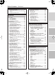
Table of Contents Getting Started Important Safety Instructions ..........................2 Precautions ........................................................3 Features .............................................................6 Supplied Accessories .......................................8 Connecting the Supplied Power Cord ............ 8 Before Using the RDC-7.1.................................9 Installing the Batteries .................................... 9 Using the Remote Controller ...............
Table of Contents—Continued Using the Remote Controller......................... 78 Enjoying Internet Radio................................. 80 Playing a Music File Saved on the Net-Tune Server ......................................................... 82 Configuring the Music Server........................ 84 Setup Menu Setup Menu...................................................... 86 OSD Map (MAIN A)....................................... 86 OSD Map (MAIN B).......................................
Features Amplifier Features • 192 kHz/24-Bit DAC for All Channels • Apogee Master Clock—the best in the industry—for the highest quality D/A conversion available • 8 Balanced XLR Outputs for the highest, most stable, noise-free signal transfer possible • Color-Coded 7.1 Multi-Channel Inputs and Pre Outs • 5 12V DC Trigger Outputs and 3 IR Inputs/ Outputs Audio/Video Features • THX Ultra2 Certified • THX Surround EX, DTS-ES Discrete/Matrix 6.
Features—Continued • Re-Equalization and the “Re-EQ” logo are trademarks of THX Ltd. • “Net-Tune” is a trademark of Onkyo Corporation. • Windows Media and the Windows logo are trandemarks, or registered trademarks of Microsoft Corporation in the United States and/or other countries. • Intel and Pentium are registered trademarks of Intel Corporation. • MPEG Layer-3 audio coding technology licensed from Fraunhofer IIS and THOMSON multimedia. • “XiVA” is a registered trademark of Imerge Limited.
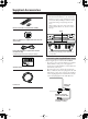
Supplied Accessories Make sure you have the following accessories: Remote Controller & Three Batteries (AA/R6) Precautions during unpacking • The unit is extremely heavy, so be careful when lifting it so as not to cause an injury. Do not lift or move the unit by holding it at the door on the front panel. Doing so may damage the front door. • When packaged, the door on the front panel is taped to the unit. Before use, be sure to remove this tape.
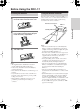
Before Using the RDC-7.1 Installing the Batteries 1 To open the battery compartment, press the small hollow and slide off the cover. Using the Remote Controller To use the remote controller, point it at the RDC-7.1’s remote control sensor, as shown below. The RDC-7.1’s [Standby] indicator flashes while a signal is being received from the remote controller. Remote control sensor RDC-7.1 ) m (5 ft.
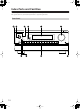
Index Parts and Facilities Here is an explanation of the controls and displays on the front panel of the RDC-7.1. The specifications for your model may differ due to regional requirements. Front Panel Master Volume Standby/On On Standby Pure Audio Zone 2 (GRN ) Rec/ Zone 3 ( RED) Power On Off DVD Video 1 Video 2 Video 3 Video 4 Video 5 Video 6 Video 7 Tape 1 Tape 2 Tuner Phono CD Net Audio Open/Close AV Controller 10 RDC-7.
Index Parts and Facilities—Continued For further operational instructions, see the pages indicated in brackets [ ]. 1 Power switch [52] Getting Started Press to turn on and off the main power supply for the RDC-7.1. When the RDC-7.1 is turned on with the [Power] switch, the [Standby] indicator lights. • Before turning on the power, check to make sure that all cords are properly connected.
Index Parts and Facilities—Continued Inner Panel Caution: The front door of the AV Controller is motorized. Use the [Open/Close] button to open or close the door. Manually opening or closing the door, or moving the AV Controller while holding the door, will cause the door to malfunction or break. USA, Canadian, and Australian models Zone 2 Rec/ Zone 3 Off Display DSP Dimmer Tuning Preset Tuning Mode Memory Setup Enter Exit Phones Clear AV Controller RDC-7.1 AV Controller RDC-7.
Index Parts and Facilities—Continued When not using either Rec/Zone 3 or Zone 2, press that button and then press the [Off] button to turn off the signal. If the Rec/Zone 3 or Zone 2 signal is turned on and the connected component is not turned on, the electric signal will still be sent through the circuitry and the excess load may cause deterioration of the audio signal. D Display button [56] Press to display information about the current input source signal.
Index Parts and Facilities—Continued Rear Panel The design of rear panel varies depending upon region for which the model is intended. For models intended for USA, Canada, and Australia, refer to “Using the RDC-7.1 with Option Boards” on page 146.
Index Parts and Facilities—Continued (Only available as option for the USA model.) These jacks are for connecting the FM indoor antenna and the AM loop antenna that are supplied with the RDC-7.1. A HDMI IN/OUT (Only available as option for the USA model.) This interface can transfer digital audio and video signals simultaneously. The terminal can be connected to the HDMI terminal on components such as DVD player, set top box (B tuner), projector, and digital TV.
Index Parts and Facilities—Continued Remote Controller (Amp Mode) The RDC-7.1’s remote controller is a multipurpose device that can be used to control not just the RDC-7.1 but your other AV components as well. This section explains how its various operating modes can be used to control the RDC-7.1. When you use the Net-Tune mode, see page 78 for details.
Index Parts and Facilities—Continued T All CH ST button This button is used to select the Pure Audio listening mode. G Test Tone, CH SEL, Level– & Level + buttons These buttons are used to adjust the level of each speaker individually. These functions can be set only with the remote controller. The [Level –] and [Level +] buttons are also used to adjust the volume in Zone 2 or Zone 3. H Audio SEL button This button is used to select the audio input signal format (e.g., analog, digital, etc.).
Speaker Placement Basic Speaker Placements for Home Theater and the Function of Respective Speakers The RDC-7.1 has many excellent features to recreate a clear three-dimensional sound image and lively sound movement. This enables you to enjoy, at home, the rich sound effects of a live theater or concert hall performance. When playing a DVD, you can enjoy sound effects provided by DTS or Dolby Digital, depending on the recording format.
Speaker Placement—Continued Placing the Speakers To fully enjoy surround sound, the configuration and placement of the speakers used are important. Be sure to read through the descriptions in the previous page and shown below. This section provides examples and descriptions that assume a typical situation.
Speaker Placement—Continued Subwoofer Using a subwoofer greatly improves the volume level and sound quality of bass sounds. The subwoofer effect depends not only on the listening position but also on the shape of the listening room. • In general, place the subwoofer in a corner of the room or at a point 1/3 the width of the room. • Play a movie or music that contains high quality bass sounds to determine the subwoofer placement.
Speaker Placement—Continued The following speaker placements will be available according to the number of speakers connected to the RDC-7.1. For the number of speaker channel, _.1 ch represents a subwoofer. 2 ch/2.1 ch This placement is used with two speakers (front left and FR FL right speakers). It is optimum for 2 ch sources including analog 2 ch, 2 ch linear PCM, Dolby Digital, DTS, DTS96/24, and AAC format sources. When the number of channels in the source is 3.
Speaker Placement—Continued Connection Examples The RDC-7.1 has two speaker terminal blocks for speaker system [A] and [B]. This allows you to build two 7.1 ch home theater systems, and various speaker placements and connections are also available. For example, some channels of either speaker system can be used for another room (Zone 2), or you can select one of two speaker systems for playback according to the source. When you use two speaker systems, you have to associate the speakers with the zone (e.g.
Speaker Placement—Continued Main room A: 7.1 ch speaker system and the two additional front speakers connected through the biamp connection (when you want to use either the 7.1 ch speakers or the additional front speakers according to the source) FL C FR 1-1.Speaker Config ===================== FR SW FL Main room A SL SR SBL SBR Speaker A a.Front L/R :Main A b.Center :Main A c.Surr L/R :Main A d.Surr Back :Main A 2ch e.Subwoofer :Main A Speaker B f.Front L/R :Main A g.Center :Not Used h.
Speaker Placement—Continued Main room A: 7.1 ch from speaker system [A] and additional subwoofer and surround speakers from speaker system [B] (suitable for enjoying more powerful and lively surround sound in main room A); Main room B: two front speakers from speaker system [B] using the bi-amp connections FL FL FR C SW SW Main room A SL SR SL SR SBL SBR FR Main room B 1-1.Speaker Config ===================== Speaker A a.Front L/R :Main A b.Center :Main A c.Surr L/R :Main A d.
Connecting a Power Amplifier Connecting a Power Amplifier Using RCA Type Cables You can connect the power amplifier that has RCA type input terminals to the RDC-7.1 using RCA type cables. Two RCA type input terminal sets (A and B) are available for this connection. The PRE OUT A terminals reflect the mode settings configured for the “Speaker System [A].” DIGITAL IN RDC-7.
Connecting a Power Amplifier—Continued Check the instruction manual that came with your power amplifier and verify that the input pin assignments are compatible with those for the RDC-7.1. 1. Connecting the output terminal Match the pins and insert the terminal until you hear a “click.” Ensure that it is secure by gently pulling it. Connecting a Power Amplifier Using XLR Type Cables You can connect the power amplifier that has XLR (balanced) type input terminals to the RDC-7.1 using XLR type cables.
Connecting a Power Amplifier—Continued Using Bi-amp Connection When you use bi-wiring-enabled speakers for the front speakers, you can make the bi-amp connection. In this connection, the front and surround back speaker terminals on the power amplifier will be used for tweeter and woofer, respectively. This connection allows you to obtain high quality sound as well as maximum treble and bass performance from the tweeter and woofer, enriching your sound experience.
Connecting Antennas This feature requires the tuner terminal board [K] to be inserted in the RDC-7.1. This chapter explains how to connect the supplied indoor FM antenna and AM loop antenna, and how to connect commercially available outdoor FM and AM antennas. Connecting the Indoor FM Antenna The supplied indoor FM antenna is for indoor use only.
Connecting Antennas—Continued Connecting the AM Loop Antenna Connecting an Outdoor FM Antenna The supplied indoor AM loop antenna is for indoor use only. If you cannot achieve good reception with the supplied indoor FM antenna, try using a commercially available outdoor FM antenna instead. 1 Assemble the AM loop antenna, inserting the tabs into the base, as shown. FM 75 Notes: Connect both wires of the AM loop antenna to the AM push terminals, as shown.
Connecting AV Components Types of Connection Cables and Terminals In addition to the conventional terminals, the RDC-7.1 has various terminals that are capable of next-generation digital transmission. Before connecting AV components to the RDC-7.1, make sure that your cable type matches the terminal shape and the signal type and that the cable length is appropriate for the placement of your connected components.
Connecting AV Components—Continued • The audio input signal from the LAN port will be output only to the AUDIO OUT terminals as an analog source. • When you play the audio signal from the PH or AUDIO IN terminals in Zone 3, the input source will be output only to the AUDIO OUT terminals as an analog source. Similarly, in this connection, you can record only the audio signal as an analog source through the AUDIO OUT terminals.
Connecting AV Components—Continued Connecting Monitors such as TV or Projector For USA and Canadian models, this type of connection is only possible if an option board that has an appropriate terminal is installed. • This section describes the connections for displaying the video source or the operating information of the RDC-7.1 on a monitor device such as a TV or projector. Before making a connection, check the terminal types on the monitor device and acquire the necessary cables by referring to page 31.
Connecting AV Components—Continued Connecting a DVD Player For USA and Canadian models, this type of connection is only possible if an option board that has an appropriate terminal is installed. • When connecting a DVD player to the RDC-7.1, make connections for video and audio signals using digital and analog terminals. Before making connections, refer to pages 30, 31 for correct connections.
Connecting AV Components—Continued Connecting a DVD Recorder or Digital VCR (VIDEO 1) For USA and Canadian models, this type of connection is only possible if an option board that has an appropriate terminal is installed. • When connecting a DVD recorder or digital VCR to the RDC-7.1, make connections for video and audio signals using digital and analog terminals. Before making connections, refer to pages 30, 31 for correct connections.
Connecting AV Components—Continued Connecting a VCR (VIDEO 2, VIDEO 3) For USA and Canadian models, this type of connection is only possible if an option board that has an appropriate terminal is installed. • When connecting a VCR to the RDC-7.1, make connections for video and audio signals. Before making connections, refer to pages 30, 31 for correct connections. • This section shows the connection example when you use the VIDEO 2 or VIDEO 3 as an input.
Connecting AV Components—Continued Example for connecting with the VIDEO 3 as input VCR When connecting to other audio terminals within the same terminal section, configure the audio input settings accordingly using the Audio Assign sub-menu (See page 98).
Connecting AV Components—Continued Connecting a DBS Tuner, DBS TV, or BS/CS Tuner For USA and Canadian models, this type of connection is only possible if an option board that has an appropriate terminal is installed. • When connecting a DBS tuner, DBS TV, or BS/CS tuner to the RDC-7.1, make connections for video and audio signals using digital and analog terminals. Before making connections, refer to pages 30, 31 for correct connections.
Connecting AV Components—Continued Connecting a CD Player, Turntable or Tuner • When connecting a CD player to the RDC-7.1, make connections using digital or analog terminals. Before making connections, refer to pages 30, 31 for correct connections. This section shows the connection example when you use the default audio input assignment settings.
Connecting AV Components—Continued Connecting a Recording Device such as MD Recorder, DAT Deck, CD Recorder or Cassette Deck Installation and Connections • When connecting a MD recorder, DAT deck or CD recorder to the RDC-7.1, make connections using digital or analog terminals. Before making connections, refer to page 30 for correct connections. • Connect a cassette or DAT tape deck to TAPE1, and an MD or CD recorder to TAPE 2. • When you connect a cassette deck to the RDC-7.
Connecting AV Components—Continued Connection Using the i.LINK (AUDIO) Terminal ( ) (Other than Chinese model) What is i.LINK i.LINK is an appellation of IEEE1394, which is the digital interface standard defined by the Institute of Electrical and Electronics Engineers (IEEE). Connecting i.LINK (AUDIO)-supported devices allows high speed transfer of data such as digital sound between the linked devices, and their control. What is i.LINK (AUDIO) The RDC-7.1 supports “i.LINK (AUDIO)” of the i.
Connecting AV Components—Continued Interconnection of i.LINK (AUDIO)-supported Devices The i.LINK connection allows for data transfer, even if the RDC-7.1 is connected to other devices via another i.LINK (AUDIO)-supported device. You can connect up to 17 devices in a daisy chain (in-line) connection arrangement using the i.LINK connection. Example: RDC-7.1 i.LINK-ready DVD player i.LINK-ready BS tuner ...
Connecting AV Components—Continued How to Configure i.LINK Connections Selecting a Device When the i.LINK connection is ready, you can use the setup menu to select any device which is connected via i.LINK. Once you have configured the i.LINK setting, the next time you select the input source, it will be selected as the playing source. Using Remote Control 1. Press the [Input] button, and then turn the scroll wheel to select any source for setting. 2.
Connecting AV Components—Continued Connection Using HDMI Terminals This feature requires the HDMI terminal board [L] to be inserted in the RDC-7.1. About the HDMI (High Definition Multimedia Interface) The High Definition Multimedia Interface (HDMI) is an interface standard for next-generation TV, designed to connect between STB (Set Top Box) and display digitally in the home, responding to technological changes such as digitalization of TV broadcasting.
Connecting AV Components—Continued Connection example when the source selection is performed on the RDC-7.1 DVD Player with HDMI OUTPUT K L ONENT VIDEO ANTENNA IN RS 232 HDMI Y TV or Projector IN 1 PB HDMI OUT REMOTE CONTROL 12V TRIGGER OUT FM 75 A 200mA MAX. PR IN 2 B 100mA MAX. C 100mA MAX. OUT D 100mA MAX. Y E AM 100mA MAX.
-compatible AV Components The terminal on the RDC-7.1 is for connecting other IntegraRESEARCH/Onkyo components equipped with the same terminal. When a component is connected to the terminal, it can be operated by the remote controller supplied with the RDC-7.1. In addition, when you connect a component to the terminal, you can also perform the system operations given below. Power on/ready function When the RDC-7.1 is in the standby state, if an connected component is turned on, the RDC-7.
Connecting Components not Reached by the Remote Controller Signals (IR IN) – USA and Canadian models – In order to use the remote controller to control the RDC-7.1 from a remote location, you will need to prepare a multiroom kit (sold separately) such as one listed below: • Multiroom kits such as those made by Niles® and Xantech® RF Receivers can also be used with the remote controller to control the RDC-7.1 from a remote location.
Using an External Device with 12V Trigger Terminal – USA and Canadian models – You can turn on the AV devices connected to the RDC-7.1 automatically using the output signal from the 12V TRIGGER OUT terminal on the RDC-7.1. 5. Connect the Phoenix terminal firmly to the 12V TRIGGER OUT socket on the RDC-7.1.
Connecting Components not Reached by the Remote Controller Signals (IR IN/OUT) – Other than USA and Canadian models – In order to use the remote controller to control the RDC-7.1 from a remote location, you will need to prepare a multiroom kit (sold separately) such as one listed below: • Multiroom kits such as those made by Niles® and Xantech® RF Receivers can also be used with the remote controller to control the RDC-7.1 from a remote location.
Using an External Device with 12V Trigger Terminal – Other than USA and Effective Sensor Layout In this situation, you will need to use a commercially available IR emitter. Connect the mini plug of the IR emitter to the IR OUT terminal on the RDC-7.1 and then place the IR emitter on the remote sensor of the component or facing it. When the IR emitter is connected, only the signal input to the IR IN terminal is output to the IR OUT terminal. The signal input from the remote sensor on the front of the RDC-7.
Basic Operation of Remote Controller Buttons The remote controller supplied with the RDC-7.1 is a multifunctional remote controller, so you can operate not only the RDC-7.1 but also AV components connected to the apparatus and components placed in another room. The basic operations are explained here. It is recommended that you read and understand this page before starting actual operations. This explanation focuses on remote controller operations. To Operate the RDC-7.
Basic Operation of Remote Controller Buttons—Continued To Operate a Connected Component (Mode Switching) On 1 Press the [Mode] button. The [Mode] button lights. 2 Roll the scroll wheel. Standby TV Input I 1 2 3 + @.-'/ ABC DEF T V CH 4 5 6 - GHI JKL Indication on the lower line changes to indicate the selected component mode.
Connecting the Power/Basic Operations • Before you plug in the RDC-7.1, confirm that all connections have been made properly. • Turning on the power may cause a momentary power surge, which might interfere with other electrical equipment on the same circuit, such as computers. If this happens, use a wall outlet on a different circuit. • The RDC-7.1 is shipped with the main power (Power) switch in the on position ( On ). When the power cord is plugged in for the first time, the RDC-7.
Connecting the Power/Basic Operations—Continued Operating with Remote Controller 1 Standby TV Input I 1 2 3 + @.-'/ ABC DEF T V CH 4 5 6 - GHI JKL MNO 7 8 9 PQRS TUV WXYZ +10 0 Clear Main A Main B T V VOL # Direct Tuning --/--- Custom Zone 3 Scroll wheel Mode Macro Zone 2 Mode Input Dimmer TV Input Top M en rv Se u er Men u Aud io CH Enter Disc VOL E xi Prev CH A DJ + Re t turn Gu up 2 Roll the scroll wheel to select a device to play.
Connecting the Power/Basic Operations—Continued Adjusting the Brightness of the Front Display Master Volume Standby/On On Standby Pure Audio Zone 2 (GRN ) Rec/ Zone 3 ( RED) Power On DVD Off Zone 2 Rec/ Zone 3 Video 1 Off Video 2 Display Video 3 Video 4 DSP Video 5 Dimmer Video 6 Tape 1 Video 7 Tuning Preset Tape 2 Tuning Mode Memory Tuner Setup Phono CD Enter Open/Close Net Audio Exit Phones Clear AV Controller Dimmer On RDC-7.
Connecting the Power/Basic Operations—Continued Macro Zone 2 Mode Input Dimmer TV Input Sleep Top M en rv Se u er CH A Enter Disc Exi Prev CH Re t turn VOL id e Gu p Setu Display Muting Random Rec Main A Main B Audio Subtitle Angle Last Memory Surround CH SEL Sleep Men u Aud io DJ + THX All CH ST Stereo Repeat A-B Search Memory Pure A Direct DSP To change the individual speaker volumes temporarily, follow the procedure given below.
Connecting the Power/Basic Operations—Continued When an input source other than FM or AM is selected: Input Master Volume Standby/On On Standby Pure Audio Program format* Zone 2 (GRN ) Rec/ Zone 3 ( RED) Power On DVD Off Zone 2 Rec/ Zone 3 Video 1 Off Video 2 Display Video 3 Video 4 DSP Video 5 Dimmer Video 6 On Tape 1 Video 7 Tuning Preset Tape 2 Tuning Mode Memory Standby Tuner Setup Phono CD Enter Open/Close Net Audio Exit Phones Clear TV Input I AV Controller 1
Connecting the Power/Basic Operations—Continued The RDC-7.1 accepts analog, digital, i.LINK (AUDIO) and multichannel signals for audio input. You can choose the kind of signal to be played for a specific device. For Zone 2, the RDC-7.1 accepts only analog and digital signals for audio input. 1 Input 2 Audio SEL Press the [Input] button, and then roll the scroll wheel to select the input source you want to set. Press the scroll wheel and then press the [Audio SEL] button.
Using the Listening Modes Types of Listening Modes Listening modes on the RDC-7.1 enable you to enjoy movie theater or concert hall quality sounds in your room. The RDC-7.1 provides the following listening modes. Before playing a source in optimal sound, be sure to complete the Speaker/Output Setup (See pages 92-94). Direct This mode allows you to enjoy pure sounds straight from an original source. Every channel of the audio input source will be output “as is” to respective channels.
Using the Listening Modes—Continued be used with CDs, DVDs, and LDs with the mark. DTS NEO:6 This mode enables 6.1 channel playback of music and movies recorded in 2 channels. A broad frequency band is allocated to each channel, and every channel is kept very independent. This mode can be set to the Cinema mode, best designed for playing movies, and the Music mode, best designed for listening to music. The sources recorded in 5.1 channels are played in NEO:6.
Using the Listening Modes—Continued TV Logic This mode is suitable for television programs broadcast from studios. You may feel as if you are sitting in a television studio. All of the surround sounds are enhanced, and conversations are output clearly. Listening Modes for Listeners Using Headphones Dolby Headphone This mode makes headphones reproduce dynamic surround sound effects like 5.1 channel speakers. The listening mode used before putting on headphones is applied to the headphones.
Using the Listening Modes—Continued 3 The RDC-7.1 provides various listening modes. Note: The available modes depend on the input signal you selected.
Listening to Radio Broadcasts This feature requires the tuner terminal board [K] to be inserted in the RDC-7.1. Using the Tuner One of the features of the RDC-7.1 that is most frequently used is its ability to play FM and AM broadcast radio stations. The RDC-7.1 provides a number of listening modes perfect for listening to the radio and getting the most out of your audio system.
Listening to Radio Broadcasts—Continued Selecting a Preset Radio Station Tuner Preset When using the RDC-7.1: Master Volume Standby/On 1 On Standby Pure Audio Zone 2 (GRN ) Rec/ Zone 3 ( RED) Tuner Power On DVD Off Zone 2 Rec/ Zone 3 Video 1 Off Video 2 Display Video 3 DSP Video 4 Dimmer Video 5 Video 6 Tuning Video 7 Preset Tape 1 Tuning Mode Memory Tape 2 Tuner Setup Phono CD Enter Clear Open/Close Net Audio Press [Tuner] input source button on the RDC-7.1.
Listening to RDS Broadcasts (European models only) Listening to RDS Broadcasts RDS reception is available only on the European model and only in areas where RDS broadcasts are available. What is RDS? RDS stands for Radio Data System and is a type of FM broadcasting. RDS was developed within the European Broadcasting Union (EBU) and is available in most European countries. Many FM broadcasting stations now transmit the RDS signals, which provide the additional information required.
Listening to RDS Broadcasts (European models only)—Continued 4 Tuner Enter Master Volume Standby/On On Standby Pure Audio Zone 2 (GRN ) Rec/ Zone 3 ( RED) Power On DVD Off Zone 2 Rec/ Zone 3 Video 1 Off Video 2 Display Video 3 DSP Video 4 RT/PTY/TP Video 5 Video 6 Tuning Video 7 Preset Tape 1 Tuning Mode Memory Tape 2 Tuner Setup Phono CD Open/Close Net Audio Enter Exit Phones Clear AV Controller RT/PTY/TP Enter RDC-7.1 / Press the [Enter] button dial. The RDC-7.
Enjoying Multichannel Playback The multichannel playback feature requires the multichannel terminal board [E] to be inserted in the RDC-7.1. The RDC-7.1 can be connected to two devices, such as a DVD player, that deal with multichannel sounds (5.17.1 channels). To use multichannel connections, you need to specify settings on the Input Setup menu. In addition, you can set listening modes as you prefer. Enjoy multichannel playback in the main room. How to Set Up Specify the input source type.
Enjoying Multichannel Playback—Continued Playing Back in Multichannel Sound Zone 2 Input CH Top M en rv Se er - Men u Aud io Exi Prev CH A DJ + u CH Enter Disc E xi Prev CH Re t turn VOL Re t turn VOL id e Gu p Setu Display VOL / Muting id e Gu p Setu Random Rec Main A Main B Audio Subtitle Angle Last Memory Muting Surround Random Rec Main A Main B Audio Subtitle Angle Last Memory Surround THX Repeat A-B All CH ST Stereo A-B Search Memory Pure A D
Enjoying Movies and Music in the Remote Zone (Zone 2/3) You can connect speakers and amplifiers for the remote zone, and enjoy different sources in a remote zone (Zone 2 or Zone 3). There are two ways to enjoy in a remote zone: 1 Connect the pre-main amplifier or receiver for Zone 2 or Zone 3 to the RDC-7.1.
Enjoying Movies and Music in the Remote Zone (Zone 2/3)—Continued 4 • You can enjoy a different source in a remote zone while a 7.1 channel source is being played in the main room. • Adjust the volume level on the RDC-7.1 (not on the power amplifier). Main Room Power amp Set the Setup menu. 1. On the Setup menu (See page 95), select “Speaker/Output Setup” → “Audio Output Assign,” and set the terminal to which the component is connected to “Zone 2 Out” or “Zone 3 Out.” 2.
Enjoying Movies and Music in the Remote Zone (Zone 2/3)—Continued Operating with the Remote Controller When operating with the remote controller, how to operate depends on the location of Zone 2 or Zone 3, or the distance from the RDC-7.1. • Point the remote controller at the infrared receiver on the RDC-7.1, and then operate the controller. • Install a remote controller sensor in Zone 2 or Zone 3 through an IR connection (See pages 46-49).
Recording a Source The RDC-7.1 can not only record the playing source but can also record a source while playing another source. You can also combine a video and audio to create a new source. Signals that can be output to a video/audio recording device vary with the type of jack connected. Check the following conditions before starting recording: Audio • Signals (analog) from the ETHERNET, PH, or AUDIO IN jacks are output only to the AUDIO OUT jacks.
Recording a Source—Continued Some steps can also be operated on the remote controller, but described here are operations on the RDC-7.1. Notes: • No surround effects can be recorded. • No DVD or any sources whose copyright is protected can be recorded. • There are some restrictions on recording of digital audio/video signals. Refer to the manual of your recording component. • If recorded as analog signals, DTS signals are recorded as noise, so never record signals from a DTS-compatible CD or LD.
3 Press the [Rec/Zone3] button, and within 3 seconds, select the source to be recorded with input source buttons. Pressing the [Rec/Zone 3] button makes the [Standby] indicator blink for 3 seconds. Select the target sources while the indicator is blinking. The name of the source to be recorded is indicated in the display window. Audio/video recording is enabled on the component for which “Rec Out” was specified in step 2. 4 Prepare the component for audio/video recording (recorder side).
Connecting Net Audio – USA, Canada, and Australian models – You can enjoy Net Audio when the ETHERNET terminal board [B] (for Net Audio) is inserted. About Net-Tune The RDC-7.1 can be used as a Net-Tune client on a standard Ethernet network, allowing you to play music (MP3, WAV) stored on your Net-Tune server such as Integra NAS-2.3 Network Audio Server through the RDC-7.1. If your network is connected to the Internet, you can also tune into Internet radio stations.
Connecting Net Audio – USA, Canada, and Australian models –—Continued Notes: • To use Internet radio with the RDC-7.1, your broadband Internet connection needs to be up and running and able to access the Web. Please consult your ISP if you have any problems with your Internet connection. • The RDC-7.1 uses DHCP and AutoIP to configure its network settings automatically. If you want to configure these settings manually, see page 122. • The RDC-7.
Connecting Net Audio – Other than USA, Canada, and Australian models – About Net-Tune A Net-Tune server is a computer server running NetTune system protocol, including a Net-Tune-compatible home server or a PC with Net-Tune Central installed. The RDC-7.1 can be used as a Net-Tune client on a standard Ethernet network. By installing IntegraRESEARCH’s Net-Tune Central server software on your computer, you can play all of your MP3, WMA, and WAV files through the RDC-7.1.
Connecting Net Audio – Other than USA, Canada, and Australian models – —Continued Notes: • To use Internet radio with the RDC-7.1, your broadband Internet connection needs to be up and running and able to access the Web. Please consult your ISP if you have any problems with your Internet connection. • The RDC-7.1 uses DHCP and AutoIP to configure its network settings automatically. If you want to configure these settings manually, see page 122. • The RDC-7.
Connecting Net Audio – Other than USA, Canada, and Australian models – —Continued Using the Remote Controller Scroll wheel To select Net-Tune mode, press the [Mode] button, and then roll the scroll wheel until “NET-T” appears on the display.
Connecting Net Audio – Other than USA, Canada, and Australian models – —Continued 1 Number/letter buttons E Stop These buttons are used to enter numbers and letters when searching for music in your Net-Tune server. 2 Mode button button This button is used to stop playback. F Random button This button is used for random playback. 3 Up/Down/Left/Right / / / & Enter buttons These buttons are used to navigate Internet radio and Net-Tune server menus.
Connecting Net Audio – Other than USA, Canada, and Australian models – —Continued 4 Net Audio Master Volume Standby/On Enter On Standby Pure Audio Zone 2 (GRN ) Rec/ Zone 3 ( RED) Power On DVD Off Zone 2 Rec/ Zone 3 Video 1 Off Video 2 Display Video 3 DSP Video 4 Video 5 Video 6 Tuning Dimmer Tape 1 Video 7 Preset Tape 2 Tuning Mode Memory Tuner Setup Phono CD Enter Open/Close Net Audio Exit Phones Clear AV Controller On RDC-7.1 Standby TV Input I 1 2 3 + @.
Connecting Net Audio – Other than USA, Canada, and Australian models – —Continued 7 Press the [Enter] button. Buffering starts with the following message displayed. 3 Press the [Enter] button. The preset is now complete. Enter Enter OSD Choosing a Preset Internet Radio Station 1 While neither the [Input] button nor [Mode] button is illuminated, roll the scroll wheel to select IRD (Internet Radio). 2 Use the remote controller’s [CH Disc +/–] button to select the preset.
Connecting Net Audio – Other than USA, Canada, and Australian models – —Continued On “Disconnected” The Net-Tune server may not start or the server connected to previously may not be found. Confirm the connections between router, the Net-Tune server, and the RDC-7.1. Start the Net-Tune server or select another server referring to “Select Server” on “Music Server Submenu” (See page 99).
Connecting Net Audio – Other than USA, Canada, and Australian models – —Continued You can use the music file data saved on the Net-Tune server to select which tracks to play.
Connecting Net Audio – Other than USA, Canada, and Australian models – —Continued Configuring the Music Server 4 Enter The music server settings can be made while you select the music server as an input source. Use the [ ]/[ ] buttons to select the “Music Server” sub-menu, then press the [Enter] button. The setup screen for the sub-menu appears. Enter On Standby TV Input I 1 2 3 + @.
Connecting Net Audio – Other than USA, Canada, and Australian models – —Continued Internet Radio Memo Operations Music Server Memo 85
Setup Menu When making the various settings required to configure your RDC-7.1 for optimum performance, you can use either the OSD Menu that appears on your television monitor or you can use the display on the front of the RDC-7.1. The OSD Menu is a settings menu that is displayed on your TV monitor. The RDC-7.1 is equipped with an independent Setup Menu not only for Main room A but also for Main room B and Zone 2 room, which allows you to specify settings for each room.
Setup Menu—Continued Reference pages 4.Audio Adjust ===================== 1.Tone Control 119 5.Preference ===================== 1.Volume Setup 2.Headphone Level Setup 120 3.OSD Setup 4.OSD Position Setup Menu Main A Setup ===================== 0.Hardware Setup 1.Speaker/Output Setup 2.Input Setup 3.Listening Mode Setup 4.Audio Adjust 5.Preference 6.i.LINK Setup 7.Network Setup 8.Lock/Version 6.i.LINK Setup ===================== 1.Wakeup Setup 2.OSD for DVD 3.OSD for DVD (Zone 2) 4.
Setup Menu—Continued OSD Map (MAIN B) Reference pages Main menu Main B Setup ===================== 0.Hardware Setup 1.Speaker Setup 2.Input Setup 3.Audio Adjust 4.Preference 0.Hardware Setup ===================== 1.TV Format Setup 1.Speaker Setup ===================== 1.Speaker Crossover 2.Speaker Distance 3.Level Calibration 4.THX Audio Setup 2.Input Setup ==Input:XXXXXXXXX==== 91 93 94 100 1.Listening Mode Preset 2.Delay 102 3.Audio Adjust ===================== 1.Tone Control 119 4.
Setup Menu—Continued OSD Map (ZONE 2) The Zone 2 settings shown on this page can be made when you perform the following settings in the “MAIN A” setup menu. • Under the “Speaker/Output Setup → Audio (Video) Output Assign” menu, when you select the output terminal setting to “Zone 2 Out.” 0.Hardware Setup ===================== 1.TV Format Setup 1.Input Setup ==Input:XXXXXXXXX==== Reference pages 91 100 1.Listening Mode Preset 102 Setup Menu 2.Delay 103 Zone 2 Setup ===================== 0.
Setup Menu—Continued Navigating the Setup Menu You can change Setup Menu settings using the buttons on the front panel and on the remote controller. The illustrations here represent the remote controller. OSD Main A Setup ===================== 0.Hardware Setup 1.Speaker/Output Setup 2.Input Setup 3.Listening Mode Setup 4.Audio Adjust 5.Preference 6.i.LINK Setup 7.Network Setup 8.Lock/Version Front panel display 1.Speaker/Output Setup ===================== 1.Speaker Configuration 2.Speaker Crossover 3.
Hardware Setup In this section, you will perform the initial settings for the following scenarios. • When you want to change the RDC-7.1’s remote control ID. • When you want to fix the TV Format setting to PAL or NTSC. • When you want to fix the AM Frequency Step setting to 9 kHz or 10 kHz. Remote ID This section explains how to change the RDC-7.1’s remote control ID. You may need to change this if the RDC-7.1’s remote controller interferes with other IntegraRESEARCH components located in the same room.
Speaker/Output Setup The RDC-7.1 provides a wide range of variations in speaker connections and speaker settings, so you have to specify speaker settings according to conditions of each variation. For proper selection of an AV device connected at switching of the input type, you also need to allocate “audio output” and “video output” to each input type. If this allocation is incorrect, the desired component will not play a selected input source.
Speaker/Output Setup—Continued The settings in the Speaker Crossover sub-menu can be configured for both “Main A” and “Main B.” Front L/R, Center, Surr L/R, Surr Back Specify a threshold frequency in Hz for bass sounds from each speaker to be output from the subwoofer. When no subwoofer is used, (Speaker A) Front L/R is automatically set to “Full Band,” and bass sounds from each speaker are output from the front speakers. You can also set other speakers to “Full Band.
Speaker/Output Setup—Continued Depth When setting “Notch Filter” above to “On,” the notch filter becomes effective at the value you specify. You can specify intervals of 0.5 dB in a range from –15 dB to 0 dB. The default is –10 dB. Width The available setting values are calculated based on the values specified in the “Frequency” and “Depth” settings above. You can choose any values according to your favorite sound.
Speaker/Output Setup—Continued This setting is allowed only when “Main 2ch” is selected from the Speaker Configuration sub-menu. Place two surround back speakers as close together as possible, measure the distance, and set the value (see the figure). The maximum effects will be realized by THX’s ASA* technology. Analog 1-5 Set the analog audio output jacks of “AUDIO OUT 1-5.
Speaker/Output Setup—Continued Opt 1 Out, Opt 2 Out, Coax 1 Out, Coax 2 Out Composite Video 1-3, S-Video 1-3 Specify a setting for “DIGITAL OUT OPTICAL 1-2” and “DIGITAL OUT COAXIAL 1-2.” You can select from Tape 1 Rec Out, Tape 2 Rec Out, Video 1 Rec Out, Video 2 Rec Out, Video 3 Rec Out, Zone 2 Out, Zone 3 Out, and Not Used. This is a setting for the composite video output jacks (VIDEO OUT 1-3) and S video output jacks (S VIDEO OUT 1-3).
Input Setup Items described here are set when you press the input source buttons. The RDC-7.1 is equipped with several types of jacks in addition to the standard audio and video jacks, and multiple jacks are provided for each type. You may freely assign input sources such as CD, PHONO, TUNER, TAPE 1, TAPE 2, and VIDEO 1-6 to these jacks.
Input Setup—Continued Follow procedures below to change any setting: 1 Press the [Input] button, and then roll the scroll wheel to select the input source that you want to set. 2 Press the scroll wheel, and then press the [Setup] button. The Main Menu appears onscreen. 3 Use the [ ]/[ ] buttons to select “Input Setup,” and then press the [Enter] button. The sub-menu is displayed. 2.Input Setup ==Input:XXXXXX======= 1.Audio Assign 2.Video Assign 3.Listening Mode Preset 4.Character Edit 5.
Input Setup—Continued Subwoofer Sensitivity This item appears when the multichannel terminal board [E] is inserted. The following are also settings for “Multichannel 1” or “Multichannel 2” (cannot be specified separately for each input source). Some DVD decks output the LFE channel at 15 dB lower than the other channels in the multichannel output. The level setting under the Level Calibration sub-menu is applied to the analog and digital inputs as well as the multichannel input.
Input Setup—Continued 2: Select the device connected to the “HDMI IN 2” jack. When selecting this, the video signal from the HDMI IN 2 terminal will also be output to the HDMI OUT terminal. VIDEO: Select this when you want the video signal such as Composite Video, S Video, and Component Video to be output from the HDMI OUT terminal. Last: Select this when you want video signal from the device you last selected to be output. No: Select this when no device is connected.
Input Setup—Continued D.F. Mono Here, you can specify the listening mode for playing digital signals such as Dolby Digital and AAC recorded in monaural. This option can be set for Main B and Zone 2 as well as for Main A. You can select from the listening modes listed below: (Main A/B) Pure Audio, Direct, Stereo, Mono (Default), Mono Movie, Enhance, Orchestra, Unplugged, Studio-Mix, TV Logic, All Ch Stereo, Full Mono, Dolby VS, and Last. (Zone 2) Direct, Stereo, Mono, Dolby VS, and Last.
Input Setup—Continued IntelliVolume Sub-menu When multiple devices are connected to the RDC-7.1, the volume may vary for a device even when volume settings on the RDC-7.1 are identical. Reducing the variance in the volume level will allow you to enjoy sounds at the same volume level without adjusting the volume control on the RDC-7.1. 12V Trigger Assign Sub-menu When the 12V TRIGGER OUT jack on the RDC-7.
Listening Mode Setup Mono Setup Sub-menu This sub-menu allows you to configure the audio effect and playback options when you play a source in the Mono listening mode. a. Re-EQ/Academy This option allows you to configure whether the Re-EQ or Academy effect is applied or not. Use these effects when you do not want to overemphasize the treble sound. This option can also be set for Zone 2. Off (Default): The effects are not applied.
Listening Mode Setup—Continued b. Multiplex Input Channel This option allows you to select the preferred audio channel when the input is the AAC/Dolby Digital sound multiplex signal. This option can also be set for Zone 2. The input channel setting made here will be applied to all the listening modes for the Dolby Digital and AAC input signal “1+1” sources. Main (Default): The main channel is preferred for output. Sub: The sub-channel is preferred for output. Main+Sub: The main and sub-channel are output.
Listening Mode Setup—Continued This option defaults to “A.” Direct, Pure Audio Setup Sub-menu This sub-menu allows you to configure the audio effect and playback options when you play a source in the Direct or Pure Audio listening mode. a. Front Speaker This option configures the front speakers to use when playing the source in the Direct or Pure Audio listening mode. Select the speakers you want to use.
Listening Mode Setup—Continued • When the “(Speaker A) Surr Back” is set to “Bi-Amp for Front” or “Not Used” in the Speaker Configuration submenu, this option will not be displayed. Dolby EX: Plays a 5.1ch source as a 6.1 or higher channel source using the Dolby Digital EX mode. PL IIx Movie (Default): Plays a 5.1ch source as a 6.1 or higher channel source using the Dolby Pro Logic IIx Movie mode.
Listening Mode Setup—Continued This sub-menu allows you to configure the audio effect and playback options when you play DVD-Audio that is input from the i.LINK(AUDIO) interface. This sub-menu appears when the i.LINK(AUDIO) terminal board [A] is inserted. a. LFE Level This option allows you to set the bass level for the i.LINK(IEEE1394):DVD-Audio listening mode. The LFE level setting made here will be applied to all of the i.LINK(IEEE1394):DVD-Audio input signals.
Listening Mode Setup—Continued h. Subwoofer This option configures the subwoofer to use when the RDC-7.1 plays DVD-Audio. Select the terminal to which the subwoofer you want to use is connected. This setting can be made when the “(Speaker A) Subwoofer” is set to an option other than “Not Used” in the Speaker Configuration sub-menu. However, when the “(Speaker B) Subwoofer” is set to an option other than “Main A” in the Speaker Configuration sub-menu, the available options will be “A” or “Not Used.
Listening Mode Setup—Continued This option configures the surround back speakers to use when the RDC-7.1 plays a Super Audio CD. Select the speakers you want to use. This setting can be made when the “(Speaker B) Surr Back” is set to “Main A” in the Speaker Configuration sub-menu. However, when the “(Speaker A) Surr Back” is set to “Bi-Amp for Front” or “Not Used,” this setting will not be displayed.
Listening Mode Setup—Continued f. Front Speaker This option configures the front speakers to use when playing the source in the Dolby Digital listening mode. Select the speakers you want to use. This setting can be made when the “(Speaker B) Front L/R” is set to “Main A” in the Speaker Configuration sub-menu. A (Default): Outputs the source from the front speakers configured to “Speaker A.” B: Outputs the source from the front speakers configured to “Speaker B.
Listening Mode Setup—Continued c. Re-EQ This option allows you to configure whether the Re-EQ effect is applied or not. Use this effect when you do not want to overemphasize the treble sound. Off (Default): The effect is not applied. On: Adjusts the soundtrack in which the treble is overemphasized, so that the sound is optimized for home theater. d. Front Speaker This option configures the front speakers to use when playing the source in the DTS listening mode. Select the speakers you want to use.
Listening Mode Setup—Continued • When the “(Speaker A) Surr Back” is set to “Bi-Amp for Front” or “Not Used” in the Speaker Configuration sub-menu, this option will not be displayed. Dolby EX: Plays a 5.1ch source as a 6.1 or higher channel source using the Dolby Digital EX mode. PLIIx Movie (Default): Plays a 5.1ch source as a 6.1 or higher channel source using the Dolby Pro Logic IIx Movie mode.
Listening Mode Setup—Continued This sub-menu allows you to configure the audio effect and playback options when you play a 2ch input source in the Dolby Pro Logic IIx or DTS NEO:6 listening modes. This setting can be made when the “(Speaker A) Center” or “(Speaker A) Surr Back” setting is set to an option other than “Not Used” in the Speaker Configuration sub-menu. • When the “(Speaker A) Surr Back” is set to “Bi-Amp for Front” or “Not Used,” the PLII mode will be used instead of the PLIIx mode. a.
Listening Mode Setup—Continued h. Center Speaker This option configures the center speaker to use when playing the source in the Dolby Pro Logic IIx or DTS NEO:6 listening modes. Select the speaker you want to use. This setting can be made when the “(Speaker B) Center” is set to “Main A” in the Speaker Configuration sub-menu. A (Default): Outputs the source from the center speaker configured to “Speaker A.” B: Outputs the source from the center speaker configured to “Speaker B.
Listening Mode Setup—Continued c. THX Mode (2ch) This option allows you to select which THX mode the RDC-7.1 will use when applying the THX effect to the signal. THX Cinema: This mode is suitable for theater movies that are recorded and edited so that they are optimized for playing in a large space such as a movie theater. Games Mode: In this new mode for the THX Ultra2, the RDC-7.1 plays a 2ch game source as a 7.1 or higher channel source. d.
Listening Mode Setup—Continued a. Front Effect This option allows you to turn off the reverb for the front speakers. This is useful when playing live material that already contains live reverberation as the added reverb simply blurs the original sound. When the Front Effect is turned off, no reverb is added to the front left, front right, and center speakers and the original reverberation can be heard as it is. On (Default): The Front Effect is turned on and the reverb is added.
Listening Mode Setup—Continued a. Re-EQ/Academy e. Surr Bk Speaker This option allows you to configure whether the Re-EQ or Academy effect is applied or not in the IntegraRESEARCH original listening mode. Use these effects when you do not want to overemphasize the treble sound. Off (Default): The effects are not applied. Re-EQ On: Adjusts the soundtrack in which the treble is overemphasized, so that the sound is optimized for home theater.
Listening Mode Setup—Continued b. Front Speaker This option configures the front speakers to use when playing the source. Select the speakers you want to use. This setting can be made when the “(Speaker B) Front L/R” is set to “Main A” in the Speaker Configuration sub-menu. A (Default): Outputs the source from the front speakers configured to “Speaker A.” B: Outputs the source from the front speakers configured to “Speaker B.
Audio Adjust You can adjust bass, mid, and treble notes for each speaker set. • For any speaker set to “Not Used” in the Speaker Configuration sub-menu, no associated setting item is displayed. Front Bass Option for adjusting bass notes from front L/R speakers. Specify at 1 dB intervals in a range from –12 dB to +12 dB. The default is “0.” This option can also be set for Zone 2. Front Mid Option for adjusting mid notes from front L/R speakers. Specify at 1 dB intervals in a range from –12 dB to +12 dB.
Preference This menu allows you to configure the listening mode settings including audio effects and playback options. Volume Setup Sub-menu a. Volume Display You can switch the volume indication between an absolute value and a relative value. Absolute (absolute value): Displayed in a range from 0 to 100. Relative (relative value) (Default): Displayed in a range of –∞ dB, –81.5 dB, –80 dB......18.0 dB. An absolute volume value of 82 is equivalent to a relative volume value of 0 dB. a.
i.LINK Setup This menu can be used when connecting to an IntegraRESEARCH i.LINK (AUDIO)-ready device. Wakeup Setup a. Wakeup on i.LINK (IEEE1394) Specify connecting condition on standby of the RDC-7.1. Enable: To be left connected. Disable (Default): To be disconnected while the RDC-7.1 is on standby to save electricity. for Zone 2, or it will be output in analog format when any source is selected for Zone 2. Enable: Enables the DVD Output for Zone 2 function.
Network Setup This menu appears when the ETHERNET terminal board [B] (for Net Audio) is inserted. If using a broadband router (DHCP function), you need not perform “7. Network Setup” because the DHCP function on the RDC-7.1 is defaulted to “Enable.” When the DHCP function for the broadband router is set to “Disable,” network setup is required. In this case, you have to be knowledgeable about the network.
Client Sub-menu While the system sending information is called a server, the machine receiving the data is called a “client.” Multiple clients can be connected to a single server. From the viewpoint of Net-Tune Central, the RDC-7.1 is a client. a. Client Name Confirm the client name used on the Net-Tune system. The client name is assigned by the RDC-7.1. You cannot change the assigned name. b.
Operating IntegraRESEARCH/Onkyo Products Using the Remote Controller The RC-554M/555M remote controller is a useful tool that can operate not only the RDC-7.1, but also all the other components of your home theater. To operate any component other than the RDC-7.1 with the RC-554M/ 555M remote controller, press the [Mode] button and use the scroll wheel to select the component to operate.
Operating IntegraRESEARCH/Onkyo Products Using the Remote Controller—Continued F Repeat button This button is used to turn on the DVD player. 2 Standby button This button is used to set the DVD player to Standby. 3 Number/letter buttons These buttons are used to enter title, chapter, and track numbers and to enter times for locating specific points in time. 4 Mode button This button is used with the scroll wheel to select the remote controller modes.
Operating IntegraRESEARCH/Onkyo Products Using the Remote Controller— Continued Boxed numbers are for MiniDisc mode (See page 127). CD Mode CD mode is used to control an Onkyo CD player connected to the RDC-7.1 via . To select CD mode, press the [Mode] button, and then roll the scroll wheel until “CD” appears on the display.
Operating IntegraRESEARCH/Onkyo Products Using the Remote Controller— Continued F Play [ ] button This button is used to start CD playback. 8 Rec [●] button This button is used to start MiniDisc recording. 9 Repeat button G Stop [ ] button This button is used to stop CD playback. H Random button This button is used with the random playback function. This button is used to set the repeat playback functions. 0 Eject [ ] button This button is used to set eject the MiniDisc.
Operating IntegraRESEARCH/Onkyo Products Using the Remote Controller— Continued 1 Mode button Tape Mode Tape mode is used to control an Onkyo cassette recorder connected to the RDC-7.1 via . To select Tape mode, press the scroll wheel, placing your remote controller into “AMP” mode.
Using the Remote Controller with Other Components You can use the RDC-7.1’s remote controller (RC554M/555M) to control your other AV components, including those made by other manufacturers. To do this you can: • Enter a remote control code for the component that you want to control (e.g., DVD, TV, VCR). • Learn commands directly from the other component’s remote controller (see page 136). • Use the Macro function to learn a sequence of actions (see page 137). 5 1 2 3 @.
Using the Remote Controller with Other Components—Continued Remote Control Codes When two or more codes are given, try each one in turn, and choose the one that works best.
Using the Remote Controller with Other Components—Continued VCR Control code Manufacturer Control code Manufacturer Control code Universum 4021, 4024 Aiwa 2012, 2046, 2047 Jensen 2013 Vortec 4017 Akai 2003, 2004, 2022 JVC Wela 4025 Zehnder 4020 2033, 2041, 2044, 2045, 2047 2005, 2006, 2007, 2009, 2032, 2035, 2040, 2048 Alba Kaisui 2033 Zenith 4032 Anitech 2033 Kendo 2041, 2046 ASA 2034 Kenwood 2005, 2006, 2007, 2009 Baird 2036 Kodak 2010 Bell & Howell 2007 Loewe 20
Using the Remote Controller with Other Components—Continued VCR TV Control code Manufacturer Control code Admiral 1026, 1040, 1062 RCA 2001, 2002, 2003, 2008, 2010, 2013, 2021, 2023, 2025, 2026, 2027 Akai 1002, 1067 Akura 1045 Alba 1035, 1043 Realistic 2007, 2008, 2010, 2011, 2012, 2017 Rex 2048 Amplivision 1063 Roadstar 2033, 2043 Amstrad 1035, 1067 Runco 2019 Amtron 1009 Saba 2040, 2048 Anam National 1003, 1009 Saisho 2028, 2041 Anitech 1035 Salora 2030 AOC 1004, 100
Using the Remote Controller with Other Components—Continued TV TV Control code Manufacturer Control code Manufacturer Control code Loewe 1014, 1040, 1055 Quasar 1003, 1012, 1031 Techwood 1004, 1006, 1012 Quelle 1036, 1039, 1054, 1055, 1058, 1059, 1068 Teknika 1004, 1005, 1006, 1007, 1009, 1022, 1025, 1031, 1070 Teleavia 1066 Telecaption 1024 Luxman 1004, 1006 LXI 1001, 1006, 1010, 1014, 1016, 1017, 1034 M Electronic 1035, 1053, 1062, 1063 Magnadyne 1040, 1067, 1068 Magnafon 106
Using the Remote Controller with Other Components—Continued Controlling a Satellite Tuner On On, Standby Controlling a VCR Standby Number buttons On On, Standby TV Input I Standby TV Input I 1 2 3 + 1 2 3 + @.-'/ ABC DEF T V CH @.
Using the Remote Controller with Other Components—Continued Controlling a TV Controlling a Cable Receiver Standby Input Number buttons 1 2 3 + @.-'/ ABC DEF T V CH 4 5 6 - GHI JKL * TV CH +/–* 8 9 TUV WXYZ +10 0 Clear T V VOL TV VOL / * TV Input 1 2 3 + @.
Using the Remote Controller with Other Components—Continued Learning Commands from Another Remote Controller 5 You can teach the RDC-7.1’s remote controller new commands simply by transmitting commands from another remote controller one at a time. For example, by transmitting the Play and Stop commands from your CD player’s remote controller, the RDC-7.1’s remote controller can be taught to transmit those commands when its Play [ ] and Stop [ ] buttons are pressed in CD mode.
Using the Remote Controller with Other Components—Continued 5 On the remote controller, press the buttons whose actions you want to program into the macro in the order you want them performed. To program the CD example in the left column into a macro: press the scroll wheel, press the [On] button, roll the scroll wheel to select CD, press the scroll wheel, and then press the Play [ ] button. Actions are numbered from 1 to 8.
Using the Remote Controller with Other Components—Continued Running Macros Programmed macros can be run as follows. 1 Press the [Macro] button. 2 Roll the scroll wheel to select the macro’s number, and then press the scroll wheel. The actions in the macro are performed in the order in which they were programmed. 5 Roll the scroll wheel to select a character, and then press the scroll wheel to set it. The following characters are available.
Other Settings for the Remote Controller Adding New Remote Controller Modes You can add additional modes (DVD, TV, VCR, CBL, SAT) to the remote controller. This is useful if, for example, you have several DVD players or TVs. Reordering the Remote Controller Modes You can change the order in which the remote controller modes appear when you roll the scroll wheel. The position of the AMP mode cannot be changed. 1 Custom 1 Custom 2 3 4 Press and hold the [Custom] button for more than three seconds.
Other Settings for the Remote Controller—Continued Deleting Remote Controller Modes Assigning Remote Controller Modes You can delete remote controller modes that you don’t need, such as modes for components that you don’t have. The AMP mode cannot be deleted. You can change the combination in selecting the input source and remote controller mode simultaneously using the scroll wheel.
Other Settings for the Remote Controller—Continued Resetting the Remote Controller You can reset the remote controller to its default settings. Custom 2 3 4 Press and hold the [Custom] button for more than three seconds. The remote controller enters Custom mode. Custom Press and hold the [Custom] button for more than three seconds. The remote controller enters Custom mode. 2 Roll the scroll wheel to select “SETUP,” and then press the scroll wheel.
Other Settings for the Remote Controller—Continued Changing the Remote Controller’s Control ID This section explains how to change the remote controller’s ID. You may need to change this if the RDC-7.1’s remote controller interferes with other IntegraRESEARCH/ Onkyo components located in the same room. Note: If you change the remote controller’s ID, be sure to select the same ID on the RDC-7.1. For details on setting up the RDC-7.
Relationship Between Input Source and Listening Mode Note: Available listening modes may differ depending on your region and the option board installed. Dolby Digital Input Signal Format Button Type of source Listening mode PCM Multichannel Multichannel (*/2) (Other than */2) CD, TV, LD, VHS, MD, Vinyl, Radio, Cassette, Cable, Satellite, etc. Dolby Digital/AAC 2ch 1/0 AAC 1+1 Analog Multichannel 5.1ch 7.1ch DVD-Audio, Super Audio CD DVD, Digital cable/satellite, etc.
Relationship Between Input Source and Listening Mode—Continued DTS Input Signal Format Button Multichannel Multichannel (Other than (*/2) */2) DTS96/24 2/0 1/0 Type of source Listening mode Multichannel Multichannel (Other than (*/2) */2) Matrix 2ch 1/0 Discrete/ Matrix DVD, LD, CD, etc.
Relationship Between Input Source and Listening Mode—Continued i.LINK(IEEE1394): SACD i.LINK(IEEE1394):DVD-Audio Input Signal Format Button Multichannel Multichannel (*/2) (Other than */2) Type of source Listening mode 2/0 1/0 1+1 176.
Using the RDC-7.1 with Option Boards – USA, Canada, and Australian models only – Types of the RDC-7.1 Option Boards The following option boards are available for the RDC-7.1 as of November 2004. A C DIGITAL IN B AUDIO IN G F E D DIGITAL IN OPTICAL R COAXIAL 1 L H R K J I L L 12 V TRIGGER OUT 4 PH 1 RS 232 E 5 2 2 3 3 1 6 4 4 2 7 GND R L IR IN +12 V DC PWR SUPPLY 20mA MAX.
Using the RDC-7.1 with Option Boards – USA, Canada, and Australian models only –—Continued Distribution regions (as of November 2004) (the United States and Canada) (Australia) Product number: C-NET-A Provides one Ethernet port for the Net Audio connection. Connecting the network server to the port allows you to enjoy music stored on your PC or delivered from an Internet radio broadcast. This option board will be inserted into slot B on the RDC-7.1.
Using the RDC-7.1 with Option Boards – USA, Canada, and Australian models only –—Continued Installing the Option Boards (USA and Australian Models Only) The sub-panels are fixed to the RDC-7.1 with two screws at the top and bottom, while the panel that covers slots [H] and [I] is fixed with four screws at the top and bottom. Keep the removed screws for fixing the option board. The option boards should be installed in their individual designated slots.
Troubleshooting Power Can’t turn on the RDC-7.1? • Make sure that the power cord is properly plugged into the wall outlet. And also, make sure that the other end of the power cord is properly connected to the RDC-7.1’s AC INLET. • Unplug the power cord from the wall outlet, wait five seconds or more, then plug the cord in again. The RDC-7.1 turns off as soon as it’s turned on? • The amp protection circuit has been activated.
Troubleshooting—Continued Can’t get 6.1 or 7.1 playback? • If no surround back speakers are connected, or Zone 2/3 is being used, 6.1 and 7.1 playback is not possible. • If the “SB Mode (5ch)” is available in any sub-menu of the “Listening Mode Setup” menu, make sure that it is not set to “Off” (pages 106-112). The volume cannot be set above 99? • When the levels of all speakers have been calibrated (page 94), the maximum volume setting may change.
Troubleshooting—Continued Recording Can’t record? • On your recorder, make sure the correct input is selected (e.g., digital or analog). • Make sure that proper output settings are made for the connected devices. Settings are available in the “Rec Out” of the “Audio Output Assign” and “Video Output Assign” sub-menus under the “Speaker/Output Setup” menu (pages 95, 96). Zone 2/Zone 3 Zone 2/3 has turned off? • Was the Sleep function set? The Sleep function turns off Zone 2/3 as well as the RDC-7.1.
Troubleshooting—Continued Specifications – USA and Canadian models – Error Messages “Not available with Headphones use” • Operation not allowed while a pair of headphones is connected. “Not available in this Sp Config” • Doesn’t work with the current speaker configuration. “Only available with Dolby D” • Can be used with only Dolby Digital. “Not available with this signal” • Doesn’t work with the current listening mode. “Not available with Muting” • Operation not allowed because the RDC-7.
Specifications – USA and Canadian models –—Continued Amplifier Section Tuner Section Maximum Output Level: 8.5 Vrms THD (Total Harmonic Distortion): 0.05% (1 Vrms output) Input Sensitivity and Impedance: Audio 200 mV, 50 kΩ (AUDIO IN 1-9) 2.5 mV, 50 kΩ (PHONO MM) 200 mV, 50 kΩ (MULTI IN FR/FL/ C/SR/SL/SBR/SBL) (Option) 36 mV, 50 kΩ (MULTI IN SUB) (Option) 0.5 Vp-p, 75 Ω (DIGITAL IN COAXIAL 1-6) 1.
Specifications – Other than USA and Canadian models – General Power Supply Rating: European & Australian models: AC 230-240 V, 50 Hz Asian models: AC 220-230 volts, 50 Hz AC 120 V, 60 Hz Consumption Power: European & Australian models: 100 W Asian models: 100 W Standby Power Consumption: 3.9 W Dimensions (W × H × D): 450 × 197.3 × 477.1 mm (17 11/16" × 7 3/4" × 18 13/16") Weight: 21.7 kg (47.8 lbs) Inputs: Audio Multichannel (7.
Specifications – Other than USA and Canadian models –—Continued Tuner Section FM Tuning frequency Range: Usable Sensitivity: Stereo Mono 50 dB Quieting Sensitivity: Mono Stereo Capture Ratio: Image Rejection Ratio: IF Rejection Ratio: S/N: Mono Stereo Alternate Channel Attenuation: Mono Selectivity: AM Suppression Ratio: Harmonic Distortion: Mono Stereo Frequency Response: Stereo Separation: Stereo Threshold: 87.50 to 108.00 MHz, 50 kHz steps 17.2 dBf, 2.0 µV (75 Ω IHF) 23 µV (75 Ω DIN) 11.2 dBf, 1.
Integra Research Division of Sales & Product Planning Div. : 2-1, Nisshin-cho, Neyagawa-shi, OSAKA 572-8540, JAPAN Tel: 072-831-8023 Fax: 072-831-8124 http://www.onkyo.com/ Integra Research Division of ONKYO U.S.A. CORPORATION 18 Park Way, Upper Saddle River, N.J. 07458, U.S.A. Tel: 201-785-2600 Fax: 201-785-2650 http://www.integraresearch.com ONKYO EUROPE ELECTRONICS GmbH Liegnitzerstrasse 6, 82194 Groebenzell, GERMANY Tel: +49-8142-4401-0 Fax: +49-8142-4401-555 http://www.eu.onkyo.