Contents Introduction AV Receiver TX-SR501 TX-SR501E Instruction Manual Important Safeguards................................................2 Precautions................................................................3 Supplied Accessories ................................................4 Features.....................................................................4 Before Using the TX-SR501/TX-SR501E ...............5 Controls & Connectors .............................................
WARNING: TO REDUCE THE RISK OF FIRE OR ELECTRIC SHOCK, DO NOT EXPOSE THIS APPLIANCE TO RAIN OR MOISTURE. CAUTION: TO REDUCE THE RISK OF ELECTRIC SHOCK, DO NOT REMOVE COVER (OR BACK). NO USER-SERVICEABLE PARTS INSIDE. REFER SERVICING TO QUALIFIED SERVICE PERSONNEL.
Important Safeguards—Continued 21. Replacement Parts—When replacement parts are required, be sure the service technician has used replacement parts specified by the manufacturer or have the same characteristics as the original part. Unauthorized substitutions may result in fire, electric shock, or other hazards. 22. Safety Check—Upon completion of any service or repairs to the appliance, ask the service technician to perform safety checks to determine that the appliance is in proper operation condition. 23.
Precautions—Continued 1. Recording Copyright—Unless it’s for personal use only, recording copyrighted material is illegal without the permission of the copyright holder. 2. AC Fuse—The AC fuse inside the TX-SR501/TX-SR501E is not user-serviceable. If you cannot turn on the TX-SR501/ TX-SR501E, contact your Onkyo dealer. 3. Care—Occasionally you should dust the TX-SR501/ TX-SR501E all over with a soft cloth. For stubborn stains, use a soft cloth dampened with a weak solution of mild detergent and water.
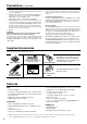
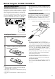
Before Using the TX-SR501/TX-SR501E Setting the Voltage Selector (Worldwide model only) The Worldwide model has a voltage selector for compatibility with power systems around the world. Before you plug in this model, make sure that the voltage selector is set to the correct voltage for your area. If it isn’t, use a small screwdriver to set it as appropriate. For example, if the voltage in your area is 120 volts (V), set the selector to “120V.” And if it’s between 220 and 230 volts (V), set it to “220–230V.
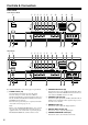
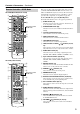
Controls & Connectors Front Panel North American Model 2 3 4 5 6 7 8 9 J K L M MASTER VOLUME STANDBY/ON STEREO DSP PRESET/ADJUST STANDBY A SPEAKERS B DIRECT SURROUND DISPLAY DIMMER DIGITAL INPUT SUBWOOFER MODE MEMORY FM MODE TUNING SPEAKER ADJUST AUDIO ADJUST CLEAR PHONES AUDIO SELECTOR DVD VIDEO 1 VIDEO 2 VIDEO 3 TAPE TUNER VIDEO 3 INPUT CD VCR S VIDEO N O P Q R VIDEO S T L AUDIO R U Other Models 1 2 3 4 5 6 7 8 9 J K L M MASTER VOLUME STANDBY/ON PO
Controls & Connectors—Continued G MEMORY button (30, 31) O PHONES jack (33) This button is used when storing and deleting radio presets. This 1/4-inch phone jack is for connecting a standard pair of stereo headphones for private listening. H FM MODE button (31) P DISPLAY button (32) This button is used to select the FM radio Stereo and Mono modes. It’s also used when deleting radio presets. This button is used to display various information about the currently selected source.
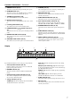
Controls & Connectors—Continued Rear Panel 1 2 COMPONENT VIDEO VIDEO 1 / 2 / 3 DVD IN IN 3 ANTENNA OUT 4 5 6 FM 75 AM AC OUTLET Y FRONT SPEAKERS B PB VIDEO 1 VIDEO 2 PR REMOTE CONTROL DIGITAL INPUT OPTICAL 2 IN OUT IN DVD SURROUND SPEAKERS FRONT SPEAKERS A L L R R CENTER SPEAKER SWITCHED 100W MAX.
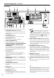
Controls & Connectors—Continued Remote Controller—RCVR Mode RC-518M (North American model) 1 2 3 J K L This page describes only those buttons that can be used to control the TX-SR501/TX-SR501E when the remote controller is in RCVR mode (Receiver mode). The other modes, and information on using the remote controller to control your other AV components, are explained on page 40. To select RCVR mode, press the [RCVR] button. For detailed information, refer to the pages in parenthesis.
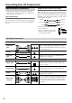
Connecting Your AV Components RCA/phono AV Connection Color Coding Before Making Any Connections RCA/phono AV connections are usually color coded: red, white, and yellow. Use red plugs to connect right-channel audio inputs and outputs (typically labeled “R”). Use white plugs to connect left-channel audio inputs and outputs (typically labeled “L”). And use yellow plugs to connect composite video inputs and outputs. • Read the manuals supplied with your AV components.
Connecting Your AV Components—Continued Which Connections To Use? Using the AC OUTLET The TX-SR501/TX-SR501E offers several connection formats for compatibility with a wide range of AV equipment. The format you choose will depend on the formats supported by your AV components. Use the following sections as a guide. When connecting video equipment, you need to make video and audio connections.
Connecting Your AV Components—Continued Connecting Your TV or Projector Connecting a DVD player ■ Using Composite Video Video Connections Use a composite video cable to connect the TX-SR501/ TX-SR501E’s VIDEO MONITOR OUT to a composite video input on your TV, as shown.
Connecting Your AV Components—Continued ■ Using Multi-channel Connections Audio Connections ■ Using Optical or Coaxial Connections • Use an optical digital audio cable to connect the TX-SR501/TX-SR501E’s OPTICAL 1 DIGITAL INPUT to the optical output on your DVD player, as shown. OR • Use a coaxial digital audio cable to connect the TX-SR501/ TX-SR501E’s COAXIAL DIGITAL INPUT to the coaxial output on your DVD player, as shown.
Connecting Your AV Components—Continued Connecting a VCR for Playback Connecting a D-VHS Recorder Video Connections Video connections • Use an S-Video cable to connect the TX-SR501/ TX-SR501E’s S VIDEO VIDEO 2 IN to the S-Video output on your VCR, as shown. Your TV must also be connected via S-Video. Use a component video cable to connect the TX-SR501/ TX-SR501E’s COMPONENT VIDEO 1/2/3 IN connectors to the component video outputs on your D-VHS recorder, as shown.
Connecting Your AV Components—Continued Connecting a VCR for Recording If your TV has AV outputs and you want to record from your TV to your VCR via the TX-SR501/TX-SR501E, make the following connections. • Use an S-Video cable to connect the TX-SR501/ TX-SR501E’s S VIDEO VIDEO 2 IN to an S-Video output on your TV, and use another S-Video cable to connect the TX-SR501/TX-SR501E’s S VIDEO VIDEO 1 OUT to an S-Video input on your VCR, as shown.
Connecting Your AV Components—Continued Connecting a Satellite/Cable Tuner, LD player, etc. Video Connections ■ Using Composite Video Use a composite video cable to connect the TX-SR501/ TX-SR501E’s VIDEO VIDEO 2 IN to the composite video output on your satellite/cable tuner, LD player, etc., as shown. • Your TV must also be connected via composite video.
Connecting Your AV Components—Continued Connecting a CD Player Connecting a Turntable ■ Using Coaxial or Optical Connections ■ Turntable with a Built-in Phono Preamp • Use a coaxial digital audio cable to connect the TX-SR501/ TX-SR501E’s COAXIAL DIGITAL INPUT to the coaxial output on your CD player, as shown. OR • Use an optical digital audio cable to connect the TX-SR501/TX-SR501E’s OPTICAL 2 DIGITAL INPUT to the optical output on your CD player, as shown.
Connecting Your AV Components—Continued ■ Turntable with an MC-type (Moving Coil) Cartridge Use an RCA/phono audio cable to connect the TX-SR501/ TX-SR501E’s L/R TAPE IN connectors to the audio outputs on your phono preamp. Use another RCA/phono audio cable to connect the phono preamp’s inputs to your MC head amp’s outputs. And use another RCA/phono audio cable to connect the MC head amp’s inputs to your turntable, as shown.
Connecting -compatible AV Components With (Remote Interactive) you can control your compatible Onkyo CD player, DVD player, or cassette recorder with the TX-SR501/TX-SR501E’s remote controller, and use the following special functions: ■ Auto Source Select ■ Auto Power On ■ Auto Power Off When you turn on an AV component connected via while the TX-SR501/TX-SR501E is in Standby, the TX-SR501/ TX-SR501E automatically turns on and selects that AV component as the input source.
Installing Your Speakers You can use two sets of speakers with your TX-SR501/ TX-SR501E: speaker set A and speaker set B. With speaker set A, which should be installed in your main listening room, and can be used with Dolby Digital or DTS surround material, you can connect front-left, front-right, center, surround-left, surround-right, surround-back, and subwoofer speakers.
Installing Your Speakers—Continued Connecting Speaker Set A Connecting Your Speakers Before you connect your speakers, read the following: • Disconnect the power cord from the wall outlet. • Read the instructions supplied with your speakers. • Pay close attention to speaker wiring polarity. In other words, connect positive (+) terminals only to positive (+) terminals, and negative (–) terminals only to negative (–) terminals.
Connecting Antenna This chapter explains how to connect the supplied indoor FM antenna and AM loop antenna, and how to connect commercially available outdoor FM and AM antennas. AM antenna push terminals FM antenna connector COMPONENT VIDEO VIDEO 1 / 2 / 3 DVD IN IN ANTENNA OUT The supplied indoor AM loop antenna is for indoor use only. 1 Assemble the AM loop antenna, inserting the tabs into the base, as shown. 2 Connect both wires of the AM loop antenna to the AM push terminals, as shown.
Connecting Antenna—Continued Connecting an Outdoor FM Antenna 3 If you cannot achieve good reception with the supplied indoor FM antenna, try a commercially available outdoor FM antenna instead. Move the small wire inside the adapter from position A to position B, as shown. Position A Wire Position B FM 75 4 Notes: • Outdoor FM antennas work best outside, but usable results can sometimes be obtained when installed in an attic or loft.
Powering Up & Setting Up the TX-SR501/TX-SR501E This chapter explains basic settings that you need to make in order to enjoy your TX-SR501/TX-SR501E after turning it on for the very first time. These include, assigning input sources to digital inputs, specifying the number of speakers, and setting the subwoofer mode, as explained on pages 24 and 25.
Powering Up & Setting Up the TX-SR501/TX-SR501E—Continued If you’ve connected a MiniDisc recorder to the TAPE inputs, you can set the TX-SR501/TX-SR501E so that “MD” appears on the display instead of “TAPE.” Simply press and hold the [TAPE] button until “MD” appears (about two seconds). Notes: • For AV components that are connected to only analog inputs, choose the “– – – –” setting. • If you don’t press the [DIGITAL INPUT] button for three seconds, the previous display reappears.
Configuring Speaker Set A This chapter describes how to configure speaker set A to achieve the best results from your surround sound system. There is no speaker configuration for speaker set B. • Before configuring, you must: —Disconnect any headphones (see page 33) —Turn off speaker set B (see page 32) —Make sure that Multich is off (see page 29) • The TX-SR501/TX-SR501E stores each setting, so you only need to configure your speakers once.
Configuring Speaker Set A—Continued 3 CABLE/SAT CD/DVD When you’ve adjusted each speaker, press the remote controller’s [TEST] button. The test tone stops and the previous display reappears. Note: If no adjustments are made for two minutes, this function is cancelled automatically and the previous display reappears.
Playing Your AV Components This chapter explains how you can play your AV components through the TX-SR501/TX-SR501E. See pages 10–19 for information on connecting your AV components to the TX-SR501/TX-SR501E. 4 To adjust the volume, use the MASTER VOLUME control, or the remote controller’s VOLUME [ ] [ ] buttons. The volume can typically be set to MIN, 1 though 79, or MAX.
Playing Your AV Components—Continued 3 AUDIO SELECTOR While the format is being displayed, use the [AUDIO SELECTOR] button to select: Auto, Analog, or Multich (DVD input source only). While “Auto” is displayed, the name of the digital input currently assigned to the input source (page 24) is displayed in parenthesis. For example, “Auto (COAX).” The possible inputs are OPT1, OPT2, and COAX. The options are explained below. Auto: The assigned digital input will have priority over the analog inputs.
Using the Tuner This chapter explains how to use the built-in tuner. You can store your favorite radio stations as presets for convenient selection. MASTER VOLUME Tuning into Radio Stations 1 TUNER PRESET/ADJUST TUNING Use the [TUNER] input selector button to select either AM or FM. In this example, the FM band has been selected.
Using the Tuner—Continued Tuning into weak FM stations If the signal strength of the station you are trying to tune into is poor, you may not be able to tune into that station, or reception may be noisy. In this case, press the [FM MODE] button to select mono mode and disable auto-tuning (the AUTO and FM STEREO indicators will go off), and try tuning manually.
Common Functions This chapter explains functions that can be used with any input source. Setting the Display Brightness With this function you can adjust the brightness of the display. SPEAKERS A & B DISPLAY DIMMER MASTER VOLUME STANDBY/ON DIRECT STEREO SURROUND DSP Use the [DIMMER] button to select: dim, dimmer, or normal brightness.
Common Functions—Continued Muting the TX-SR501/TX-SR501E (remote controller only) With this function you can temporarily mute the output of the TX-SR501/TX-SR501E. Remote controller Press the remote controller’s [MUTING] button. The output is muted and the MUTING indicator flashes on the display, as shown. • Only speakers that are included in the current configuration can be adjusted. See “Specifying the Number of Speakers” on page 25.
Using the Listening Modes With its built-in surround-sound decoders and DSP programs, the TX-SR501/TX-SR501E can transform your home listening room into a movie theater or concert hall. To get the most from surround sound, it’s important that you install and configure your speakers correctly. See “Installing Your Speakers” on page 20 and “Configuring Speaker Set A” on page 26 for information.
Using the Listening Modes—Continued The listening modes are explained below. Basic Modes Direct: The selected input source is fed directly to the poweramp stages and through to the front left and right speakers with minimal processing. Use this mode when watching an old movie that has a mono soundtrack, when listening to either the left or right channel of multilingual material, or when playing a DVD or other source that has multiplexed audio, such as a karaoke DVD.
Using the Listening Modes—Continued The options for each button are explained below: Selecting the Listening Modes You can select the listening modes by using the following buttons: [DIRECT], [STEREO], [SURROUND], [DSP], and [A.STEREO] (the last button is available only on the remote controller). [DIRECT] button • This button selects the Direct listening mode, which can be used with PCM, analog, and 96 kHz PCM sources.
Audio Adjust Functions Using the Audio Adjust Functions PRESET/ADJUST These functions only work with speaker set A. Audio Adjust provides various functions for adjusting the sound, including several especially for use with Dolby Digital, DTS, and Pro Logic II material. The following table lists the Audio Adjust functions, their ranges and default values. Function availability depends on the current source and listening mode, as listed in the “Supported listening mode” column.
Audio Adjust Functions—Continued The Audio Adjust functions are explained below. ■ Bass With this function you can boost or cut low-frequency sounds output by the front speakers from –12 dB to +12 dB in 2 dB steps. ■ Treble With this function you can boost or cut high-frequency sounds output by the front speakers from –12 dB to +12 dB in 2 dB steps.
Recording This chapter explains how to record the selected input source to an AV component with recording capability, and how to record audio and video from two different sources. Recording the Input Source You can record only to AV components that are connected to the TAPE OUT or VIDEO 1 OUT connectors. See pages 10–19 for information on connecting your AV components to the TX-SR501/TX-SR501E.
Using the Remote Controller RC-479S with Your Other AV Components RC-479S (not North America) Connecting your -compatible Onkyo CD player, DVD player, or cassette recorder to the TX-SR501/TX-SR501E via allows you to control it with the TX-SR501/ TX-SR501E’s remote controller. Since you only need to point the remote controller at the TX-SR501/TX-SR501E, you can control components that are out of sight, for example, in a cabinet. See page 19 for connection information.
Using the Remote Controller RC-518M with Your Other AV Components RC-518M (North America only) Manufacturer TV AIWA Connecting your -compatible Onkyo CD player, DVD player, or cassette recorder to the TX-SR501 via allows you to control your system with the TX-SR501’s remote controller by pointing it at the TX-SR501. This allows you to control components that are out of sight, for example, in a cabinet.
Using the Remote Controller RC-518M with Your Other AV Components—Continued Using the RC-518M If you need to enter the manufacturer’s code for your AV component into the remote controller, see page 41. 1 Point the remote controller at the TX-SR501 and use the input selector buttons to select an input source for the TX-SR501. 2 Use the remote controller’s mode buttons (i.e., [VCR], [TV], [CABLE/SAT], [CD/DVD], or [RCVR/TAPE]) to select a remote controller mode.
Using the Remote Controller RC-518M with Your Other AV Components—Continued VCR mode TV mode You must enter the appropriate manufacturer’s code (see page 41). You must enter the appropriate manufacturer’s code (see page 41). 3. 2. VCR 4. VCR control buttons Control TV if appropriate TV code has been entered 1. 2. 1. TV 3.
Using the Remote Controller RC-518M with Your Other AV Components—Continued Cable mode* Satellite mode* You must enter the appropriate manufacturer’s code (see page 41). You must enter the appropriate manufacturer’s code (see page 41). 3. 2. 3. CABLE/SAT 4. 4. Cable control buttons 1. 2. CABLE/SAT 1.
Troubleshooting Symptom Can’t turn on the TX-SR501/TX-SR501E? Possible cause Remedy The power cord is not connected. Connect the power cord to a suitable wall outlet (page 24). The [POWER] switch is set to OFF (other than North American model). Set the [POWER] switch to ON (page 24). Turn off the TX-SR501/TX-SR501E, wait five secExternal interference is affecting the TX-SR501/ onds, then try turning it on again.
Troubleshooting—Continued Symptom Possible cause Remedy A low-frequency noise or hum can be heard? The audio connecting cables at the rear of the TX-SR501/TX-SR501E are too close to the power cord. Untangle the audio cables and position them as far away as possible from the power cord. The sound is too bright or harsh and the high range is not clear. The Treble function is set too high. Adjust the Treble function (pages 29, 37). The subwoofer mode is set to OFF or is set incorrectly.
Troubleshooting—Continued Symptom Possible cause Remedy Use the [FM MODE] button to select mono mode (page 31). Reception is noisy, intermittent, and the FM STEREO indicator flashes? You’re too far away from the transmitter. Or, your FM antenna is in the wrong position or pointing in the wrong direction. Or, the station’s signal strength is poor. Adjust the position, height, and direction of your FM antenna. Install an outdoor FM antenna, preferably one with many elements.
Specifications AMPLIFIER SECTION TUNER SECTION Continuous Average Power output (FTC) All channels: 65 watts per channel min. RMS at 8 Ω, 2 channels driven from 20 Hz to 20 kHz with no more than 0.08% total harmonic distortion. 80 watts per channel min. RMS at 6 Ω, 2 channels driven from 1 kHz with no more than 0.1% total harmonic distortion.