Contents Before using AV Receiver TX-DS484 Instruction Manual Important Safeguards........................ 2 Precautions ....................................... 3 Features............................................. 4 Supplied accessories......................... 4 Before operating this unit ................. 5 Preparation Audio equipment connections .......... 6 Video equipment connections .......... 7 Connecting other devices ................. 8 Connecting speakers.......................
WARNING: TO REDUCE THE RISK OF FIRE OR ELECTRIC SHOCK, DO NOT EXPOSE THIS APPLIANCE TO RAIN OR MOISTURE. CAUTION: TO REDUCE THE RISK OF ELECTRIC SHOCK, DO NOT REMOVE COVER (OR BACK). NO USER-SERVICEABLE PARTS INSIDE. REFER SERVICING TO QUALIFIED SERVICE PERSONNEL.
21. Replacement Parts – When replacement parts are required, be sure the service technician has used replacement parts specified by the manufacturer or have the same characteristics as the original part. Unauthorized substitutions may result in fire, electric shock, or other hazards. 22. Safety Check – Upon completion of any service or repairs to the appliance, ask the service technician to perform safety checks to determine that the appliance is in proper operation condition. 23.
Features Supplied accessories 55 W/CH TO EACH OF THE FIVE CHANNELS INTO 8 OHMS, 20 Hz—20 kHz, 0.
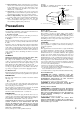
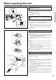
Before operating this unit Setting the AM tuning step frequency (Worldwide models only) AM FREQUENCY STEP Worldwide models are equipped with a switch that controls the AM band tuning steps. Please set this switch to match the AM band tuning step frequency in your area. U.S.A.
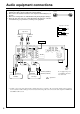
Audio equipment connections • On each pair of input jacks, a red connector (marked R) corresponds to the right • • • Audio connection cable channel, and a white connector (marked L) to the left channel. Please refer to the instruction manual of each component when making any connections. This receiver is designed for use with turntables using moving magnet cartridges. Insert the plugs and connectors securely.
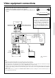
Video equipment connections • On each pair of input jacks, a red connector (marked R) corresponds to the right • • Audio connection cable channel, and a white connector (marked L) to the left channel. A yellow connector (marked V) is used for video connection. Please refer to the instruction manual of each component when making any connections.
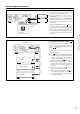
Connecting other devices • On each pair of input jacks, a red connector (marked R) corresponds to the right • • channel, and a white connector (marked L) to the left channel. A yellow connector (marked V) is used for video connection. Please refer to the instruction manual of each component when making any connections. Audio connection cable L (Left) L R (Right) R Video connection cable V (Video) V Monaural audio cable (mono) Decoder with 5.1 channel output You may connect the 5.
Connecting other devices AC outlet connection SUB WOOFER PRE OUT ANTENNA R AM COAXIAL 2 COAXIAL 1 OPTICAL (REC) OUT MONITOR OUT (PLAY) IN FRONT REMOTE CONTROL R SURROUND DVD IN VIDEO 1 IN L L R L R TAPE R CENTER DIGITAL INPUT L A CENTER SPEAKER L SURROUND SPEAKERS SWITCHED TOTAL 120W 1A MAX. GND SUB CENTER WOOFER OUT TX-DS484 B VIDEO 2 L IN R R PHONO AC OUTLETS AC120V 60Hz FM 75 L MULT I CH I NPUT V L R CD FRONT SPEAKERS U.S.A.
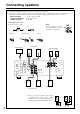
Connecting speakers • If you want to use the surround effects, connect surround speakers. For the best results, connect a center speaker. • Use FRONT SPEAKERS B terminals to connect a second pair of front speakers. • This receiver is designed to produce optimum sound quality when speakers with impedances within the specified ranges are connected. Please check the following information and choose speakers with appropriate impedances for the connections. FRONT SPEAKERS: A or B: 6 ohms min.
Positioning speakers Positioning speakers Speaker placement plays an important role in the reproduction of Surround sound. The placement of the speakers varies depending on the size of the room and the wall coverings used in the room. The illustration shows an example of a layout for standard speaker placement. Refer to this example when you position the speakers in order to experience the best of Surround sound.
Making antenna connections Connecting the antenna cable to the 75/300 ohm antenna adapter (Worldwide models) Outdoor antenna Indoor antenna 300 ohms ribbon wire 1 2 3 ✦ ✦ ✦ ✦ ✦ ✦ ✦✦ ✦ ✦ ✦ 6 3 6 mm mm mm Slit B 15mm Connecting the 300 ohm ribbon wire: Loosen the screws and wrap the wire around these screws. Then tighten the screws with a screwdriver. Connecting the coaxial cable: 1. With your fingernail or a small screwdriver, press the stoppers outward and remove the cover. 2.
Making antenna connections U.S. and Canadian models Connecting the included antennas Other models ANTENNA AM Remove the insulation at the tip of the cable, and insert the cable securely, fully to the end of the exposed tip. Connecting the FM indoor antenna: The FM indoor antenna is for indoor use only. Extend the antenna and move it in various directions until the clearest signal is received. Fix it with push pins or similar implements in the position that will cause the least amount of distortion.
Speaker setup PARAMETER SELECTOR/ PARAMETER CONTROLLER buttons Use these buttons to set the speaker parameters, such as the type and distance.
Speaker setup 4 PARAMETER CONTROLLER PARAMETER SELECTOR or or 5 PARAMETER CONTROLLER PARAMETER SELECTOR or or 6 ft PARAMETER CONTROLLER meter feet ft PARAMETER SELECTOR 7 ft PARAMETER CONTROLLER or ft PARAMETER SELECTOR 4. Press the PARAMETER SELECTOR® button to display the center speaker size parameter, and press the PARAMETER CONTROLLER √/® buttons to select “LARGE”, “SMALL” and “NONE.
Speaker setup 9 or PARAMETER CONTROLLER or PARAMETER SELECTOR 10 or PARAMETER CONTROLLER PARAMETER SELECTOR 1, 3 9. Press the PARAMETER SELECTOR® button to display the LFE LEVEL parameter, and press the PARAMETER CONTROLLER √/® buttons to set the value. You can set the LFE LEVEL parameter for the Dolby digital or DTS playback. In general, leave this parameter to 0dB. Pressing the PARAMETER CONTROLLER √/® buttons repeatedly toggles the values. Display the desired value.
Selecting a sound source Follow the steps below to select a device to play the sound source. 2. Make sure that the SPEAKERS A indicator is lit on the display. If it is not lit, press the SPEAKERS A button. (Refer to the “Speakers selector” section on the page 19 for more details.) DIMMER button Use this button to change the brightness of the display (normal or dim). 4. Adjust the volume to an appropriate level.
Selecting a sound source When Multi channel input is selected as a source 1 POWER SLEEP DIMMER SUR MODE Follow the steps below to adjust the level of each speaker if you have selected MULTI CH INPUT.
Selecting a sound source Switching between digital and analog inputs DVD Player TX-DS484 COAXIAL 2 COAXIAL 1 OPTICAL DIGITAL INPUT DVD 1 2 DVD Either a digital or analog device can be connected to the digital connector. Follow the steps below to select digital or analog according to the type of the connected device. You can assign digital input to DVD, CD, VIDEO1-2, and TAPE. With the default setting, all inputs are assigned analog.
To enjoy Surround mode or Stereo mode 2. SURROUND MODE button This button allows you to select a Surround mode. LATE NIGHT button Use this button to play sound in Dolby Digital mode (refer to page 22). VOLUME knob Use this knob to adjust the volume level.
To enjoy Surround mode or Stereo mode DOLBY PRO LOGIC Notes on DTS This surround format consists of four channels (left and right front, center, and monaural surround channels) and emphasizes the center channel. This format is very effective for panning music, conversation, and three-dimensional sound movement output from three front channels. It also simulates the atmosphere and surround effects of the sound reflected from the side and rear walls of the theater.
To enjoy Surround mode or Stereo mode Setting the Surround mode parameters LATE NIGHT If you play a movie at a low volume at night, set this parameter to “ON” to narrow the dynamic range of the sound to make it easier to hear. The Late Night function works only with source material that contains necessary Dolby Digital information. Press the LATE NIGHT button. The LATE NIGHT indicator appears on the display. To cancel the LATE NIGHT function, press the LATE NIGHT button again.
Tuning in a radio station √ TUNING ® MASTER VOLUME DO P W N PARAMETER SELECTOR U STANDBY/ON STANDBY POWER ON PARAMETER CONTROLLER PRESET TUNING OFF A SPEAKERS B SURROUND MODE LATE NIGHT MEMORY DIMMER FM MODE CLEAR PHONES MULTI CH INPUT DVD VIDEO 1 VIDEO 2 TAPE FM AM PHONO TREBLE BASS CD AV RECEIVER FM AM TX-DS484 FM MODE Manual tuning 1 FM 1. Press the FM or AM button. 2. Use the TUNING √/® buttons to change the frequency. ® (up).............. the frequency increases.
Using preset radio stations AM FM √ TUNING ® POWER SLEEP DIMMER SUR MODE MULTI-CH INPUT INPUT SELECTOR TAPE TUNER PHONO DVD CD MASTER VOLUME PRESET TUNER DO P W N PARAMETER SELECTOR U STANDBY/ON VIDEO-1 VIDEO-2 CD DVD TUNER √ PRESET ® STANDBY DISC PARAMETER CONTROLLER POWER ON PRESET TUNING OFF A SPEAKERS B SURROUND MODE LATE NIGHT MEMORY DIMMER FM MODE TAPE CLEAR MULTI CH INPUT PHONES DVD VIDEO 1 VIDEO 2 TAPE FM AM CH SEL TREBLE BASS TEST TONE CD PHONO LEVEL
Recording a source You can record analog Audio, but not digital audio. Make sure that you have made a correct analog connection. You cannot record the source connected to MULTI CH INPUT jack. If you select another device as the input source during recording, the input signal from that device will be recorded. You cannot record audio source along with the surround effects.
Recording a source Recording data from a video disc player (or a video camcorder) to VCR 1 MASTER VOLUME P DO W N PARAMETER SELECTOR U STANDBY/ON Video disc programs can be recorded onto a VCR (VIDEO 2). STANDBY PARAMETER CONTROLLER POWER ON PRESET TUNING OFF A SPEAKERS B SURROUND MODE LATE NIGHT MEMORY DIMMER MULTI CH INPUT PHONES VIDEO 1 DVD VIDEO 2 TAPE FM AM PHONO 1. Load a disc in the video disc player or DVD player, and insert a blank tape in the VCR (VIDEO 2). 2.
Troubleshooting guide If a problem occurs while you are using the remote controller, first try to operate the front panel controls on the main unit to make sure that it is not due to a malfunction (or worn out batteries) in the remote controller. Trouble Cause • • No power. • • Power on but no sound. • • No sound from the center speaker, or very minimal sound. Howling when the volume is turned up. Rough or scratchy sound. High range is not clear.
Specifications AMPLIFIER SECTION Continuous Average Power output (FTC) All channels: 55 watts per channel min. RMS at 8 ohms, 2 channels driven from 20 Hz to 20 kHz with no more than 0.08% total harmonic distortion. 70 watts min. RMS at 6 ohms, 2 channels driven from 1 kHz with no more than 0.1% total harmonic distortion. Continuous Power output (DIN) 75 watts × 5 at 6 ohms Maximum Power output (EIAJ) 100 watts × 5 at 6 ohms Total Harmonic Distortion: 0.08% at rated power (Front) IM Distortion: 0.
Control positions and names 1 2 3 4 6 5 7 8 10 9 MASTER VOLUME P DO W N PARAMETER SELECTOR U STANDBY/ON STANDBY PARAMETER CONTROLLER POWER ON PRESET TUNING OFF A SPEAKERS B SURROUND MODE LATE NIGHT MEMORY DIMMER FM MODE CLEAR MULTI CH INPUT PHONES DVD VIDEO 1 VIDEO 2 TAPE FM AM PHONO BASS TREBLE CD AV RECEIVER 17 18 a 16 b 15 14 13 c 12 d e f g h TX-DS484 11 i j Display Front panel For more information about buttons or knobs, refer to the pages liste
Remote controller RC-427S 7 8 POWER 1 2 3 SLEEP DIMMER SUR MODE MULTI-CH INPUT 9 INPUT SELECTOR TAPE TUNER PHONO DVD VIDEO-1 VIDEO-2 CD PRESET TUNER CD 10 DVD DISC 11 4 TAPE CH SEL 13 MUTING VOLUME 14 6 REMOTE CONTROLLER RC-427S 15 30 11. 12. 13. 14. 12 TEST TONE 5 LEVEL 1. 2. 3. 4. 5. 6. 7. 8. 9. 10. 15.
Using the remote controller Listening to the radio POWER 1 SLEEP SUR MODE DIMMER MULTI-CH INPUT INPUT SELECTOR TAPE TUNER PHONO DVD VIDEO-1 VIDEO-2 2 PRESET TUNER CD 1. Press the TUNER button. 2. Use the PRESET buttons to select the desired station.
Sales & Product Planning Div. : 2-1, Nisshin-cho, Neyagawa-shi, OSAKA 572-8540, JAPAN Tel: 072-831-8111 Fax: 072-833-5222 ONKYO U.S.A. CORPORATION 200 Williams Drive, Ramesy, N.J. 07446, U.S.A. Tel: 201-825-7950 Fax: 201-825-8150 E-mail: onkyo@onkyousa.com ONKYO EUROPE ELECTRONICS GmbH Industriestrasse 20, 82110 Germering, GERMANY Tel: 089 84 93 20 Fax: 089 84 93 226 E-mail: info@onkyo.de ONKYO CHINA LIMITED Units 2102-7, Metroplaza Tower I, 223 Hing Fong Road, Kwai Chung, N.T.