Contents Before using AV Receiver TX-SR500 TX-SR500E Instruction Manual Important safeguards ........................................ 2 Precautions ........................................................ 3 Features ............................................................. 4 Supplied accessories ......................................... 4 Before using the unit ........................................ 5 Facilities and connections Index to parts and controls ...............................
WARNING: TO REDUCE THE RISK OF FIRE OR ELECTRIC SHOCK, DO NOT EXPOSE THIS APPLIANCE TO RAIN OR MOISTURE. CAUTION: TO REDUCE THE RISK OF ELECTRIC SHOCK, DO NOT REMOVE COVER (OR BACK). NO USER-SERVICEABLE PARTS INSIDE. REFER SERVICING TO QUALIFIED SERVICE PERSONNEL.
21. Replacement Parts – When replacement parts are required, be sure the service technician has used replacement parts specified by the manufacturer or have the same characteristics as the original part. Unauthorized substitutions may result in fire, electric shock, or other hazards. 22. Safety Check – Upon completion of any service or repairs to the appliance, ask the service technician to perform safety checks to determine that the appliance is in proper operation condition. 23.
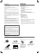
Features Precautions 1. Recording Copyright Recording of copyrighted material for other than personal use is illegal without permission of the copyright holder. 2. AC Fuse The fuse is located inside the chassis and is not user-serviceable. If power does not come on, contact your Onkyo authorized service station. 3. Care From time to time you should wipe the front and rear panels and the cabinet with a soft cloth.
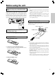
Before using the unit Setting the voltage selector (Worldwide models only) Worldwide models are equipped with a voltage selector to conform with local power supplies. Be sure to set this switch to match the voltage of the power supply in your area before plugging in the unit. Determine the proper voltage for your area: 220-230 V or 120 V. If the preset voltage is not correct for your area, insert a screwdriver into the groove in the switch.
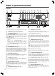
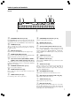
Index to parts and controls Front panel 1 2 ! @ 3 45 6 78 9 0 #$ ^& ~ * For operational instructions, refer to the page indicated in brackets. 7 1 This button is used to assign the radio station that is currently tuned in to a preset channel or delete a previously preset station. POWER switch (other than USA and Canadian models) [17] Turns on the main power supply for the TX-SR500/TX-SR500E. The TX-SR500/TX-SR500E enters standby state and the STANDBY indicator lights up.
Index to parts and controls Display a b c i ! e g d f h SPEAKERS A/B buttons [21, 26] j a (SPEAKERS) A/B indicators [21, 26] Press SPEAKERS A/B to turn on/off the speaker system A/B. The (SPEAKERS) A/B indicators corresponding to the selected speaker system light up. You can use SPEAKERS A and B simultaneously. Shows the current speaker system in use. @ Flashes when the mute function is active. PHONES jack [26] This is a standard stereo jack for connecting stereo headphones.
Index to parts and controls Rear panel 1 ANTENNA 2 3 4 FM 75 AM L L DIGITAL INPUT COAXIAL OPTICAL 1 VIDEO 2 REMOTE CONTROL IN VIDEO 1 OUT DVD MONITOR OUT IN IN SURROUND SPEAKERS FRONT SPEAKERS B FRONT SPEAKERS A 2 5 AC OUTLET CENTER SPEAKER L VIDEO R R R VOLTAGE SELECTOR S VIDEO 120 V IN OUT OUT IN IN IN SURR FRONT CENTER L L SUBWOOFER PRE OUT 220-230 V R R CD TAPE VIDEO 2 VIDEO 1 DVD 678 9 SUB WOOFER p q w For operational instructions, refer to the page ind
Index to parts and controls RC-479S (For models other than North American models) 1 2 3 4 5 0 = ~ ! @ Explanations on this page are for controlling the TX-SR500/ TX-SR500E. To operate other components, see “Using remote controller” on pages 34 through 35, and “Pre-programming remote controller (North American models only)” on pages 36 and 37. For operational instructions, refer to the page indicated in brackets. 1 SLEEP button [27] For setting the sleep time.
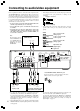
Connecting to audio/video equipment Here is explanation of how to connect the main components to the TX-SR500/SR500E in the standard manner. There are many ways that any one component can be connected, and it is up to you to decide which method best fits your situation. The directions given here are only one option and should only be thought of as such.
Connecting to audio/video equipment About the DVD, VIDEO 1, VIDEO 2 and MONITOR OUT jacks The video input/output connections are also necessary even if you make the S video input/output connections. • If the DVD player has both 5.1 channel audio outputs and 2 channel audio outputs, and you want to connect the DVD player only using the FRONT L/R jacks on the TX-SR500/TX-SR500E, use the 2 channel audio output jacks on the DVD player.
Positioning speakers/Connecting speakers Two speaker systems (FRONT SPEAKERS A and FRONT SPEAKERS B) can be connected to the Receiver. The FRONT SPEAKERS A system is to be placed in the main room, and the FRONT SPEAKERS B system is to be placed in a second room. The configuration of the FRONT SPEAKERS A system The FRONT SPEAKERS A system consists of the front left, center, and right speakers, surround left and right speakers, and subwoofer.
Positioning speakers/Connecting speakers Before connecting • Refer also to the instruction manuals of the speakers. • Be sure to connect the positive and negative cables for the speakers properly. If they are mixed up, the left and right signals will be reversed and the audio will sound unnatural. • Connect speakers with an impedance between 6 Ω and 16 Ω Connecting speakers with an impedance less than 6 Ω may damage the TX-SR500/TX-SR500E.
Connecting antennas Connecting the supplied FM and AM indoor antennas (aerials) ANTENNA ANTENNA FM 75 AM L L DIGITAL INPUT COAXIAL OPTICAL 2 1 VIDEO 2 IN REMOTE CONTROL VIDEO 1 OUT IN DVD IN MONITOR OUT SURROUND SPEAKERS FRONT SPEAKERS B FRONT SPEAKERS A AC OUTLET CENTER SPEAKER L VIDEO R R R VOLTAGE SELECTOR S VIDEO 120 V IN OUT IN IN OUT IN SURR FRONT CENTER L L SUBWOOFER PRE OUT 220-230 V R R CD TAPE VIDEO 2 VIDEO 1 DVD SUB WOOFER North American models 1 Strip a
Connecting antennas Connecting an FM outdoor antenna (aerial) If the FM reception is not very clear with the supplied antenna (aerial), connect an FM outdoor antenna (aerial) instead of the indoor FM antenna (aerial). FM outdoor antenna (aerial) Connecting coaxial cable to a 75/300 ohm antenna (aerial) adapter* 1 Strip the end of the coaxial cable. 3 5/8 in. 1/4 1/8 1/4 in. Remove the transformer wire A from slit B and insert it into slit C. AM FM 75 Slit B in. in.
Connections for remote control (z) The z terminal on the TX-SR500/TX-SR500E is for connecting other Onkyo components equipped with the same z terminal. When a component is z-connected, you can point the remote controller supplied with the TX-SR500/TX-SR500E at the sensor on the TX-SR500/TX-SR500E and operate that component without having to switch remote controllers. In addition, by connecting components to the z terminal, you can also perform the system operation given below.
Connecting the power/Turning on the AV Receiver STANDBY/ON STANDBY/ON STANDBY indicator POWER Before connecting • Make sure that all the connections from pages 10 to 16 are complete. • Turning on the AV Receiver may cause a momentary power surge, which might interfere with other electrical equipment such as computers. If this happens, use a wall outlet on a different circuit. 1. Connect the power cord (mains lead) to a wall outlet (the mains). 2.
Speaker setup SPEAKER ADJUST PRESET/ADJUST ™/£ You need to set up the speaker configuration for the speaker system connected to the FRONT SPEAKERS A connectors (see page 13). (There is no speaker configuration setup for the SPEAKERS B system.) Notes • Speaker setup cannot be done if; – Headphones are connected (see page 26), – The FRONT SPEAKERS B system is on (see page 26), – “Multi ch” is selected with AUDIO SELECTOR button, or – Connected source is played.
Speaker setup SPEAKER ADJUST PRESET/ADJUST ™/£ Setting the delay time Setting the center delay In the procedure below, select the values which approximate the actual distances. This operation consists of entering the time error between output of sound from each speaker type (front, center and surround) and arrival at the listening position. The user should measure the distance from the listening position to each speaker type and obtain the time error (delay time) based on the appropriate table.
Speaker setup SUBWOOFER MODE TEST CH SEL Setting the subwoofer mode LEVEL 5/∞ Adjusting each speaker’s relative volume balance — Test tone Press SUBWOOFER MODE on the unit. With the first press of the button, you can check the present setting. Then each press of the button changes the subwoofer mode as follows (a tip on how to select the right subwoofer mode is in parentheses): → Subwoofer Mode 1 (To output the low frequencies of all channels from the subwoofer.
Playing the connected source MASTER VOLUME dial SP A SP B SPEAKERS A/B This section shows you how to play the sources connected to the AV Receiver. You may need to see “Connecting to audio/video equipment” on page 10 while following the steps in this section. Selecting a sound source 1.
Playing the connected source DIGITAL INPUT DVD Setting the digital inputs When connecting digital source components to the DIGITAL INPUT jacks on the rear panel, assign the input source button on the front panel to either a DIGITAL INPUT OPTICAL or COAXIAL jack depending on the type of connector on the digital source components. The DVD, CD, VIDEO 1, VIDEO 2, VIDEO 3 and TAPE inputs can be assigned to the DIGITAL INPUT jacks.
Playing the connected source DIRECT DIRECT CH SEL AUIO SEL DVD AUDIO SELECTOR DVD LEVEL 5/∞ TAPE Using multi channel input The multi channel input refers to a system, which is compatible with a source component equipped with 5.1-channel outputs (DVD player, MPEG decoder, etc.), reproducing the left/right front, center and left/right surround channels from five respective speakers and outputting the subwoofer channel from SUB WOOFER (refer to page 13). 1. Press DVD. 2.
Listening to the radio There are two ways to select radio stations: • Manual tuning • Presetting radio stations then selecting the preset channels TUNING ™/£ MASTER VOLUME dial FM MODE TUNER Setting the AM tuning step frequency (Worldwide models only) You can switch the AM band tuning steps between 9 kHz and 10 kHz. The initial setting is 9 kHz. Please set the AM tuning step frequency to match the AM band tuning step frequency in your area.
Listening to the radio FM MODE MEMORY PRESET 2/3 TUNER PRESET/ADJUST ™/£ Presetting radio stations You can preset up to 30 stations. 1. Tune in the radio station you wish to preset (refer to the previous page). 2. Press MEMORY. The MEMORY indicator lights and the preset number starts flashing in the display. 3. While the MEMORY indicator is lit (for about 8 seconds), press PRESET/ADJUST ™/£ to select the preset number.
Various functions common to all the sources SPEAKERS A/B SP A/SP B PHONES jack Turning on/off the SPEAKERS A/SPEAKERS B systems MUTING Muting the sound (remote controller only) Press MUTING. You can turn on or off the speaker systems connected to the FRONT SPEAKERS A and FRONT SPEAKERS B connectors individually. Press SPEAKER A on the unit or SP A on the remote controller to turn on or off the SPEAKERS A system.
Various functions common to all the sources SLEEP DIMMER DISPLAY DIMMER Changing the display Controlling the brightness of the lights on the AV Receiver Press DISPLAY. Each time you press DISPLAY, the screen changes as follows: When an input source other than FM or AM is selected Input source + volume Program format* Input source + Listening mode (or Multich) Press DISPLAY once to initiate the program format display. Pressing the button again switches the display to the other display.
Various functions common to all the sources AUDIO SELECTOR DVD Adjusting each speaker’s relative volume balance temporarily CH SEL AUDIO SEL DVD LEVEL 5/∞ For example, follow the steps below to specify the input signal format for the DVD input 1. Press DVD. You can readjust each speaker’s relative volume balance according to your preference while listening to the sound.
Various functions common to all the sources PRESET/ADJUST ™/£ AUDIO ADJUST CINE FLTR LATE NIGHT AUDIO ADJUST ADJUST 2/3 Using the AUDIO ADJUST function The AUDIO ADJUST function adjusts the following items. • Audio quality (Bass/Treble) • Late Night On/Off • Cinema Filter On/Off Note The adjustment is not available when the listening mode is “Direct” or Multich setting is “Tone Off” (see page 23). 1. Press AUDIO ADJUST (repeatedly) until the item to be adjusted is displayed.
Enjoying the listening modes The surround sound of the AV Receiver enables you to enjoy the presence of a movie theater or concert hall in your room. Before using any surround mode, make sure the Speaker Setup configurations have been set (see page 18). The speaker configuration is very important for the surround sound. See “Positioning speakers/Connecting speakers” on page 13. For operational instructions, refer to the page 32. Following are the sound systems the AV Receiver can reproduce.
Enjoying the listening modes The input sources and available listening mode The listening modes that can be selected are variable depending on the signal formats employed with the input sources. Notes • Only “Stereo” (“Stereo” or “Direct” for PCM/Analog source) can be selected when the speaker configuration is set to “Speaker 2ch”, when headphones are used, or when speakers B is selected. • The listening mode cannot be selected when “Multich” is selected.
Enjoying the listening modes SURROUND STEREO DIRECT DSP DSP DIRECT SURROUND Selecting the listening mode See “Relationship between input sources and listening modes” on page 31. Press one of the listening mode buttons to select the listening mode. DIRECT: Set the listening mode to “Direct”. STEREO: Set the listening mode to “Stereo”.
Recording a source To record the input source signal you are currently watching or listening to Recording of video and/or audio signals can be performed on the components connected to the VIDEO 1 OUT and TAPE OUT (audio only) jacks. Recording the video from one source and the audio from another You can add the sound from one source to the video of another source to make your own video recordings.
Using remote controller You can operate the z-connected Onkyo DVD player, CD player or cassette tape deck with the remote controller provided with the TX-SR500/TX-SR500E. The graied buttons in the illustration operates the TX-SR500/TX-SR500E in any mode. The RC-478M remote controller is for USA and Canadian models, and the RC-479S remote controller is for other models. Controlling an Onkyo DVD player The z connector of the Onkyo DVD player must be connected to the TX-SR500/TX-SR500E (refer to page 16).
Using remote controller Controlling an Onkyo CD player The z connector of the Onkyo compact disc player must be connected to the TX-SR500/TX-SR500E (refer to page 16). 1. Press CD. CD CD to turn on the Onkyo 2. Press compact disc player. 3. Press the desired operation button. s: e: CD operation buttons CD operation buttons RC-479S RC-478M Starts playback of CD. Stops playback, fast forward or fast reverse. f: Fast forwards the CD. d: Fast reverses the CD. 2/8 : Lets playback pause temporarily.
Pre-programming remote controller (North American models only) You can make RC-478M remote controller to operate a product from other brand than Onkyo by storing the pre-programming code of the brand in the RC-478M.
Pre-programming remote controller (North American models only) Controlling a TV 1. Press TV mode. 2. Press to turn on the TV. TV 3. Press the desired operation button. 1–9, +10, 0 : Use to enter numeric values. OK : Confirm TV CH UP 5 : Changes the TV channel upward. TV CH DOWN ∞ : Changes the TV channel downward. TV VOL UP 3 : Increases the TV volume. TV VOL DOWN 2 : Decrease the TV volume. TV/VCR : Switches the TV/VCR inputs.
Troubleshooting Check the following guide for the possible cause of a problem before contacting service. Refer also to the respective instruction manuals of the connected components and TV. Symptoms Causes Remedies Pages The AV receiver doesn’t switch on. • The power cord (mains lead) is disconnected. • The main power is set to OFF. • There is external noise interfering with the computer circuits of the AV receiver. • Check the connection of the power cord (mains lead). • Turn on the main power.
Other Recording Tuner Troubleshooting Symptoms Causes Remedies Pages Too much noise is heard or sound is interrupted occasionally. (The FM STEREO indicator does not light steadily.) • FM stereo waves may produce a hiss noise when a certain level is reached. • The position or direction of the FM antenna (aerial) is incorrect. • The station is too weak. • Switch the frequency receiving mode to mono. • Adjust the position, height, and direction of the FM antenna (aerial).
Specifications AMPLIFIER SECTION Continuous Average Power output (FTC) 65 watts per channel min. RMS at 8 ohms, All channels: 2 channels driven from 20 Hz to 20 kHz with no more than 0.08% total harmonic distortion. Continuous Power output (DIN) 85 watts × 5 at 6 ohms Maximum Power output (EIAJ) 115 watts × 5 at 6 ohms Dynamic power output: 160 watts × 2 at 3 ohms 125 watts × 2 at 4 ohms 85 watts × 2 at 8 ohms Total Harmonic Distortion: 0.08% at rated power 0.08% at 1 watt output IM Distortion: 0.