Contents AV Receiver Before using 2 Facilities and connections 8 Setup and operation 31 Remote controller 63 Appendix 75 TX-SR701/701E TX-SR601/601E Instruction Manual Thank you for purchasing the Onkyo AV Receiver. Please read this manual thoroughly before making connections and plugging in the unit. Following the instructions in this manual will enable you to obtain optimum performance and listening enjoyment from your new AV Receiver. Please retain this manual for future reference.
WARNING: TO REDUCE THE RISK OF FIRE OR ELECTRIC SHOCK, DO NOT EXPOSE THIS APPLIANCE TO RAIN OR MOISTURE. CAUTION: TO REDUCE THE RISK OF ELECTRIC SHOCK, DO NOT REMOVE COVER (OR BACK). NO USER-SERVICEABLE PARTS INSIDE. REFER SERVICING TO QUALIFIED SERVICE PERSONNEL.
Precautions 1. Recording Copyright Recording of copyrighted material for other than personal use is illegal without permission of the copyright holder. 2. AC Fuse The fuse is located inside the chassis and is not user-serviceable. If power does not come on, contact your Onkyo authorized service station. 3. Care From time to time you should wipe the front and rear panels and the cabinet with a soft cloth.
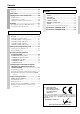
Contents Before using Important Safety Instructions ........................... 2 Precautions ......................................................... 3 Contents .............................................................. 4 Features .............................................................. 6 Supplied accessories ........................................ 7 Before using this unit ........................................ 7 Setting the voltage selector (Worldwide models only) ......
Contents Preference .........................................................56 Preference ........................................................................56 Appendix Audio Adjust ......................................................57 Troubleshooting guide ......................................75 Enjoying music in the remote zone .................60 POWER .......................................................................... 75 SPEAKERS ....................................................
Features TX-SR701/701E TX-SR601/601E Amplifier Features Amplifier Features ■ 100 W × 2 (Front)/ 100 W (Center)/ 100 W × 2 (Surround)/ 100 W (Surround Back) at 8 ohms, 20 Hz - 20 kHz, 0.
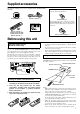
Supplied accessories Check that the following accessories are supplied with the TX-SR701/701E/ 601/601E.
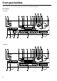
Front panel facilities Here is an explanation of the controls and displays on the front panel of the TX-SR701/701E/601/601E.
Front panel facilities For further operational instructions, see the pages indicated in brackets [ ]. POWER switch (for all models other than USA and Canadian models, and Australian models) [28] Press to turn on and off the main power supply for the TX-SR701/ 701E/601/601E. When the TX-SR701/701E/601/601E is turned on with the POWER switch, the STANDBY indicator lights. • Before turning on the power, check to make sure that all cords are properly connected.
Front panel facilities Input source buttons (DVD, VIDEO 1–4, TAPE, TUNER, CD, and PHONO (TX-SR701/701E only)) [41] These buttons are used to select the input source. Press these buttons to select the input source for the main zone. To select the input source for the remote zone (Zone 2) or recording out (Rec Out), first press the ZONE 2 or REC OUT button, and then press the desired input source button.
Front panel facilities Front panel display MUTING indicator Flashes when the mute function is turned on. Listening mode or digital input format indicators One of these indicators lights to show the format of the current input source. In addition, one of the listening mode indicators lights to indicate the current listening mode. Tuning indicators TUNED indicator Lights when a radio station is received. AUTO indicator Lights when receiving FM broadcasts in the stereo mode.
Remote controller RC-533M SEND/LEARN indicator Lights red when signals are sent by the remote controller. It also flashes when a button is pressed when the battery power is low. ON/STANDBY button [28] ON: Press to turn on the TX-SR701/701E/601/601E. STANDBY: Press to place the TX-SR701/701E/601/601E in the standby state. Be aware that pressing the STANDBY button only places the TXSR701/701E/601/601E in standby and does not turn the power completely off. SLEEP button [44] Press to set the sleep function.
Remote controller INPUT SELECTOR buttons [41] Press to select an input source. Same as the input selector buttons on the front panel of the TXSR701/701E/601/601E. The input source for each button is given here. DVD:DVD, CD:CD, V1:VIDEO1, V2:VIDEO2, V3:VIDEO3, V4:VIDEO4, V5:VIDEO5 (not used with the TXSR701/701E/601/601E), TAP:TAPE, TUN:FM/AM, PH:PHONO (not used with the TX-SR601/601E).
Connections • Be sure to always refer to the instructions that came with the component that you are connecting. • Do not plug in the power cord until all connections have been properly made. • For input jacks, red connectors (marked R) are used for the right channel, white connectors (marked L) are used for the left channel, and yellow connectors (marked V) are used for video connection. • Insert all plugs and connectors securely.
Connections TX-SR701/701E REMOTE When using CONTROL [24] the Zone 2 12V TRIGGER ZONE 2 LINE OUT terminal [21] terminals [23] Connecting antennas [29] COMPONENT VIDEO INPUT/OUTPUT [18-20] ANTENNA AM CAUTION: SPEAKER IMPEDANCE FM 75 6 OHMS MIN.
Connections Here is an explanation of typical ways to connect various components to the TX-SR701/701E/601/601E. There are many ways that any one component can be connected, and it is up to you to decide which method best fits your situation. The directions given here are only one option and should only be thought of as such. It is best to fully understand the nature of each connector and terminal as well as those of your components and their features to ascertain which method of connection is best.
Connections Connecting a DVD Player with 5.1-Channel Output ANTENNA AM FM 75 COMPONENT VIDEO INPUT 2 OUTPUT INPUT 1 Y ZONE 2 LINE OUT R PR DIGITAL IN 2 OUT OPTICAL 1 Component video output L PB COAXIAL VIDEO 3 IN VIDEO 2 OUT IN VIDEO 1 OUT IN REMOTE CONTROL DVD MONITOR OUT IN OPTICAL ZONE 2 V S 12 V TRIGG OUT Video output S video output IR IN IN COAXIAL IN IN IN OUT IN OUT IN OUT IN SURR FRONT CENTER L GND L 4.
Connections Connecting a DVD Player with 2-Channel (L/R) Audio Output ANTENNA AM FM 75 COMPONENT VIDEO INPUT 2 OUTPUT INPUT 1 Y ZONE 2 LINE OUT R PR DIGITAL IN 2 OUT OPTICAL 1 Component video output L PB COAXIAL VIDEO 3 IN VIDEO 2 OUT IN VIDEO 1 OUT IN REMOTE CONTROL DVD MONITOR OUT IN OPTICAL ZONE 2 V S 12 V TRIGG OUT Video output S video output IR IN IN COAXIAL IN IN IN OUT IN OUT IN OUT IN SURR FRONT CENTER L GND L 4.
Connections : Signal flow Component video output Video output ANTENNA 6. Satellite tuner or television (VIDEO 3) AM FM 75 S Video output COMPONENT VIDEO INPUT 2 OUTPUT INPUT 1 Y ZONE 2 LINE OUT PB L PR R 5.
Connections 8. TV monitor or projector (MONITOR OUT) ANTENNA AM FM 75 COMPONENT VIDEO INPUT 2 7.
Connections 9. Connecting video camera, etc. (VIDEO 4 INPUT) Using an RCA video cable, connect the video output jack (composite) of the device to the VIDEO 4 VIDEO jack of the TXSR701/701E/601/601E. Or if the device has an S video output jack, connect it to the VIDEO 4 S VIDEO jack of the TX-SR701/701E/ 601/601E using an S video cable. Using an RCA audio cable, connect the audio output jack of the device to the VIDEO 4 AUDIO jacks of the TX-SR701/701E/601/ 601E.
Operating components not reached by the remote controller signals (IR IN) In order to use the remote controller to control the TX-SR701/ 701E/601/601E from a remote location, you will need to prepare a multi-room kit (sold separately) such as one of those given below: • Onkyo’s Multi-Room System kit (IR Remote Controller Extension System) • Multiroom A/V distribution and control system such as those from Niles® and Xantech® Make the connections as shown below.
Connecting the remote zone (Zone 2) speakers The TX-SR701/701E/601/601E allows you to listen to two separate input sources at the same time. This allows you to, for example, place speakers in two different rooms so that two or more people can enjoy two different kinds of music at the same time. The room where the TX-SR701/701E/601/601E is actually located is referred to as the main room while the separate room is referred to as the remote zone (Zone 2).
Connections AC OUTLETS The TX-SR701/701E/601/601E is equipped with AC mains outlets for connecting the power cords from other devices so that their power is supplied through the TX-SR701/701E/601/601E. By doing this, you can leave the connected device turned on and have the STANDBY/ON button on the TX-SR701/701E/601/601E turn on and off the device together with the TX-SR701/701E/601/601E. The shape, number, and total capacity of the AC outlets may differ depending on the area of purchase.
Connecting speakers Before connecting the speakers, it is very important to place them properly for the optimum sound space for your listening pleasure. Be sure to refer to the instruction manuals that came with the speakers during placement and connection. Furthermore, be aware that for surround playback, the configuration and placement of your speakers are both very important. Subwoofer When bass sound is reproduced, its volume and quality greatly depend on subwoofer placement.
Connecting speakers Using the speaker cable labels The positive speaker terminals on the TX-SR701/701E/601/601E are color coded for easy identification. Attach the supplied speaker labels to the speaker cables, and then match the colors on the speaker cables to the corresponding terminals.
Connecting speakers Center speaker Front right speaker ANTENNA AM CAUTION: SPEAKER IMPEDANCE FM 75 6 OHMS MIN. /SPEAKER COMPONENT VIDEO INPUT 2 ZONE 2 SPEAKERS OUTPUT INPUT 1 Y ZONE 2 LINE OUT R PR DIGITAL 2 OUT OPTICAL 1 COAXIAL VIDEO 2 VIDEO 3 IN OUT IN VIDEO 1 OUT IN REMOTE CONTROL DVD MONITOR OUT IN L R R OPTICAL 12 V TRIGGER OUT V ZONE 2 SURR CENTER SURR BACK (SB) IR IN OUT IN OUT IN PRE OUT SURR FRONT R AC 230-240 V 50 Hz SWITCHED TOTAL 100W MAX.
Connecting the power Diagram for RC-533M Diagram for TX-SR701/701E (USA and Canadian models and Australian models) (All models other than USA and Canadian models and Australian models) STANDBY/ON ON STANDBY RCVR MODE STANDBY/ON STANDBY indicator STANDBY indicator MASTER VOLUME AUDIO ADJUST SETUP AUDIO ADJUST RETURN STANDBY/ON MASTER VOLUME SETUP RETURN STANDBY/ON TUNING TUNING PRESET PRESET POWER STANDBY STANDBY ON REC OUT ZONE 2 OFF LEVEL DISPLAY DIMMER STEREO LISTENING MODE SUR
Connecting antennas To use the tuner of the TX-SR701/701E/601/601E, it is necessary to prepare the supplied FM and AM antennas. • Adjustment and placement of the FM and AM antennas for better reception must be done while listening to a station broadcast. • If better reception cannot be obtained, then placement of an outside antenna is recommended. Assembling the AM loop antenna Assemble the loop antenna as shown in the illustration.
Connecting antennas Connecting an FM outdoor antenna Directional linkage Make sure to follow the general rules given below: • Keep the antenna away from noise sources (neon signs, busy roads, etc.). • It is dangerous to put the antenna close to power lines. Keep it well away from power lines, transformers, etc. ANTENNA AM Do not use the same antenna for both FM and TV (or VCR) reception since the FM and TV (or VCR) signals can interfere with each other.
Configuring the speakers / / / SETUP RETURN RETURN AUDIO ADJUST SETUP MASTER VOLUME SETUP RETURN STANDBY/ON TUNING / / / ENTER PRESET POWER STANDBY ON REC OUT OFF ZONE 2 OFF LEVEL DISPLAY RT/PTY/TP STEREO LISTENING MODE SURROUND THX DSP MEMORY FM MODE ENTER CLEAR PHONES DIRECT/ PURE AUDIO AUDIO SELECTOR DVD VIDEO 1 VIDEO 2 VCR 1 VCR 2 VIDEO 3 VIDEO 4 TAPE TUNER CD VIDEO 4 INPUT PHONO PURE AUDIO DIGITAL S VIDEO VIDEO L AUDIO R ENTER To create the optimum sound s
Configuring the speakers 4. Use the and cursor buttons to select “Subwoofer” and then use the and cursor buttons to select the subwoofer setting. Yes: Select when a subwoofer is connected. No: Select when a subwoofer is not connected. 9. Use the and cursor buttons to select “Crossover” and then use the and cursor buttons to select the crossover frequency mode setting. Adjustable Crossover for Bass Management TX-SR701/701E TX-SR701/701E/601/601E Remote controller TUNING PRESET TUNING PRESET 5.
Configuring the speakers Setting the speaker distance from your normal listening position Each speaker can be set between 1 and 30 feet (0.3 and 9 meters) in 1-foot (0.3 meter) increments. Select the setting closest to the actual distance from the speaker to your normal listening position. Note: Speakers that you selected “No” or “None” for in the “Speaker Config” menu will be disabled.
Configuring the speakers TX-SR601/601E 8. Use the and cursor buttons to select “Subwoofer” and then use the and cursor buttons to set the distance from the subwoofer speaker to your normal listening position. 1. Use the and cursor buttons to select “3. Speaker Distance” on the main menu and then press the ENTER button. The “Speaker Distance” menu appears. * Menu ***************** 1.Hardware Config 2.Speaker Config 3.Speaker Distance 4.Level Calibration 5.Input Setup 6.
Configuring the speakers 2. Use the and select “Left.” cursor buttons to (1) Remember the volume level of this noise and then press the cursor button. (Note that this can be adjusted to any level between –12 and +12 decibels in 1-decibel increments. For subwoofer, values between –15 and +12 dB can be set.) The TX-SR701/701E will now emit the pink noise from the center speaker.
Configuring the speakers Using the remote controller 1. Press the TEST button. You will hear a pink noise which will be emitted from the front left speaker. (1) Remember the volume level of this noise and then press the CH SEL button. The TX-SR601/601E will now emit the pink noise from the center speaker. (2) Using the LEVEL / buttons, adjust the volume level of the noise from the center speaker so that it is at the same level as that was emitted from the front left speaker.
Listening to Radio Broadcasts FM MODE AUDIO ADJUST TUNING / MASTER VOLUME SETUP RETURN STANDBY/ON TUNING PRESET POWER STANDBY ON REC OUT OFF ZONE 2 OFF LEVEL DISPLAY RT/PTY/TP STEREO LISTENING MODE SURROUND THX DSP MEMORY FM MODE ENTER CLEAR PHONES DIRECT/ PURE AUDIO AUDIO SELECTOR DVD VIDEO 1 VIDEO 2 VCR 1 VCR 2 VIDEO 3 VIDEO 4 TAPE TUNER CD VIDEO 4 INPUT PHONO PURE AUDIO DIGITAL S VIDEO VIDEO L AUDIO R TUNER One of the features of the TX-SR701/701E/601/601E th
Listening to Radio Broadcasts FM MODE PRESET MEMORY AUDIO ADJUST / RCVR MODE MASTER VOLUME SETUP RETURN CH STANDBY/ON TUNING PRESET POWER STANDBY ON REC OUT OFF ZONE 2 OFF LEVEL DISPLAY RT/PTY/TP STEREO LISTENING MODE SURROUND THX DSP MEMORY FM MODE ENTER CLEAR PHONES DIRECT/ PURE AUDIO AUDIO SELECTOR DVD VIDEO 1 VIDEO 2 VCR 1 VCR 2 VIDEO 3 VIDEO 4 TAPE TUNER CD VIDEO 4 INPUT PHONO PURE AUDIO DIGITAL S VIDEO VIDEO L AUDIO R TUN ENTER TUNER Presetting a radio st
Listening to RDS broadcasts (European models only) Listening to RDS broadcasts PTY program types in Europe RDS reception is available only on the European model and only in areas where RDS broadcasts are available. The text given below in parenthesis is what is actually displayed on the TX-SR701E/601E. What is RDS? RDS stands for Radio Data System and is a type of FM broadcasting. RDS was developed within the European Broadcasting Union (EBU) and is available in most European countries.
Listening to RDS broadcasts (European models only) PRESET / RT/PTY/TP AUDIO ADJUST MASTER VOLUME SETUP RETURN STANDBY/ON TUNING PRESET POWER STANDBY ON REC OUT OFF ZONE 2 OFF LEVEL DISPLAY RT/PTY/TP STEREO LISTENING MODE SURROUND THX DSP MEMORY FM MODE ENTER CLEAR PHONES DIRECT/ PURE AUDIO AUDIO SELECTOR DVD VIDEO 1 VIDEO 2 VCR 1 VCR 2 VIDEO 3 VIDEO 4 TAPE TUNER CD VIDEO 4 INPUT PHONO PURE AUDIO DIGITAL S VIDEO VIDEO L AUDIO R ENTER TUNER 4.
Selecting an Audio Component TX-SR701/701E RCVR MODE AUDIO ADJUST MASTER VOLUME SETUP VOL RETURN STANDBY/ON TUNING PRESET POWER STANDBY ON REC OUT OFF ZONE 2 OFF LEVEL DISPLAY RT/PTY/TP STEREO LISTENING MODE SURROUND THX DSP MEMORY ENTER FM MODE CLEAR PHONES DIRECT/ PURE AUDIO AUDIO SELECTOR DVD VIDEO 1 VIDEO 2 VCR 1 VCR 2 VIDEO 3 VIDEO 4 TAPE TUNER CD VIDEO 4 INPUT PHONO PURE AUDIO DIGITAL S VIDEO VIDEO L AUDIO R INPUT SELECTOR buttons MASTER VOLUME Input source
Selecting an Audio Component RCVR MODE AUDIO ADJUST MASTER VOLUME SETUP RETURN STANDBY/ON CH SEL AUDIO SEL TUNING PRESET POWER STANDBY ON REC OUT OFF ZONE 2 OFF LEVEL DISPLAY RT/PTY/TP STEREO LISTENING MODE SURROUND THX DSP MEMORY ENTER FM MODE LEVEL / CLEAR PHONES DIRECT/ PURE AUDIO AUDIO SELECTOR DVD VIDEO 1 VIDEO 2 VCR 1 VCR 2 VIDEO 3 VIDEO 4 TAPE TUNER CD VIDEO 4 INPUT PHONO PURE AUDIO DIGITAL S VIDEO VIDEO L AUDIO R TAP TAPE AUDIO SELECTOR Selecting the ty
Selecting an Audio Component Temporarily changing the speaker output levels To change the individual speaker volumes temporarily, follow the procedure given below. Each channel can be set between –12 and +12 decibels. For subwoofer, values between –15 and +12 decibels can be set. Note that the calibration settings will return to the original settings when the TX-SR701/701E/601/601E is put in standby. Using the remote controller: 1. Press the RCVR MODE button. 2.
Selecting an Audio Component SLEEP AUDIO ADJUST AUDIO ADJUST MASTER VOLUME SETUP VOL RETURN STANDBY/ON TUNING PRESET AUDIO SEL POWER STANDBY ON REC OUT OFF ZONE 2 OFF LEVEL DISPLAY RT/PTY/TP STEREO LISTENING MODE SURROUND THX DSP MEMORY FM MODE ENTER CLEAR PHONES DIRECT/ PURE AUDIO AUDIO SELECTOR DVD VIDEO 1 VIDEO 2 VCR 1 VCR 2 VIDEO 3 VIDEO 4 TAPE TUNER CD AUDIO ADJUST VIDEO 4 INPUT PHONO PURE AUDIO DIGITAL S VIDEO VIDEO L AUDIO R MASTER VOLUME PHONES AUDIO S
Selecting an Audio Component Using the tone control: To make bass and treble adjustment work for multichannel sources, you must first set the tone control to “On.” To turn on the tone control: 1. Press the SURROUND button (or SURR button on the remote controller).
Listening Modes The TX-SR701/701E/601/601E’s surround sound enables you to enjoy the presence of a movie theater or concert hall in your room. The configuration of the speakers is very important for the surround sound. Refer to “Connecting speakers” on page 25. Before using a listening mode, make sure the Speaker Config, Speaker Distance, and Level Calibration parameters have been set (see pages 31 to 36). Once the parameters have been set, it is not necessary to set them again.
Listening Modes • THX Cinema This is the conventional 5.1-channel THX format. This mode should be used only when playing back sources that were mixed for playback in large movie theater environments. • THX Surround EX “THX Surround EX - Dolby Digital Surround EX” is a joint development of Dolby Laboratories and the THX division of THX Ltd.
Listening Modes TX-SR701/701E Listening mode buttons RCVR MODE AUDIO ADJUST MASTER VOLUME SETUP RETURN STANDBY/ON TUNING PRESET POWER STANDBY ON REC OUT OFF ZONE 2 OFF LEVEL DISPLAY RT/PTY/TP STEREO LISTENING MODE SURROUND THX DSP MEMORY FM MODE ENTER CLEAR PHONES DIRECT/ PURE AUDIO AUDIO SELECTOR DVD VIDEO 1 VIDEO 2 VCR 1 VCR 2 VIDEO 3 VIDEO 4 TAPE TUNER CD VIDEO 4 INPUT PHONO PURE AUDIO DIGITAL S VIDEO VIDEO L AUDIO R Listening mode buttons Re-EQ Selecting a li
Listening Modes THX: Changes the listening mode to the THX listening mode. If the THX listening mode is selected • While playing back Dolby Digital sources Switches the THX Surround EX mode (Auto → On → Off) if the source is a THX Surround EX-compatible source. • While playing back Analog/PCM sources Switches the decoding mode (Pro Logic II Movie → DTS Neo6:Cinema) for THX processing. • While playing back DTS sources Switches the DTS-ES mode from Auto → On → Off.
Listening Modes TX-SR601/601E Listening mode buttons RCVR MODE AUDIO ADJUST MASTER VOLUME SETUP RETURN STANDBY/ON TUNING PRESET POWER STANDBY ON REC OUT OFF ZONE 2 OFF LEVEL DISPLAY RT/PTY/TP DIRECT LISTENING MODE STEREO SURROUND MEMORY DSP ENTER FM MODE CLEAR PHONES AUDIO SELECTOR DVD VIDEO 1 VIDEO 2 VCR 1 VCR 2 VIDEO 3 VIDEO 4 TAPE TUNER VIDEO 4 INPUT CD DIGITAL S VIDEO VIDEO L AUDIO R Listening mode buttons CINE FLTR Selecting a listening mode (TX-SR601/601E) •
Listening Modes DSP: Changes the listening mode for the signal type that is currently being input from the selected input source as shown below. Orchestra → Unplugged → Studio-Mix → TV Logic → All Ch Stereo → Mono → T-D → Mono Movie → Enhance → Orchestra. If pressed, the corresponding settings in the “Input Setup” menu for the selected input source is also changed (see page 54).
Input Setup RETURN SETUP RETURN AUDIO ADJUST SETUP MASTER VOLUME SETUP RETURN STANDBY/ON TUNING / / / ENTER PRESET POWER STANDBY ON REC OUT OFF ZONE 2 OFF LEVEL DISPLAY RT/PTY/TP STEREO LISTENING MODE SURROUND THX DSP MEMORY ENTER FM MODE CLEAR PHONES DIRECT/ PURE AUDIO AUDIO SELECTOR DVD VIDEO 1 VIDEO 2 VCR 1 VCR 2 VIDEO 3 VIDEO 4 TAPE TUNER CD VIDEO 4 INPUT PHONO PURE AUDIO DIGITAL S VIDEO VIDEO L AUDIO R INPUT SELECTOR buttons / / / Input source buttons This
Input Setup b. Component Video The video signal from the input jacks set at the “b. Component Video” setting is output to the COMPONENT VIDEO OUT jacks. Use this setting if you connect monitors like TV to the COMPONENT VIDEO OUT jacks on the TX-SR701/701E/601/601E. For example, when you connect the DVD player to the COMPONENT VIDEO INPUT 1 jacks, select “DVD” as input source and set “b. Component Video” to “INPUT 1.” The default settings are given below.
Input Setup The listening mode will be reset to the mode you set here after turning on the TX-SR701/701E/601/601E even if you change the listening mode using the LISTENING MODE buttons. When you set this setting to “Last Valid”, the listening mode will be the one you used before. Notes: • For “e. PCM fs 96kHz source” “f. Digital Format source” “g. D. F. Mono source” These settings will be disabled if “----” is selected at the “Digital Input” setting. • For “e. PCM fs 96kHz source” “g. D. F.
Hardware Setup Hardware Config To display the Hardware Config menu: 1. Display the main menu. 2. Use the and cursor buttons to select “1. Hardware Config” and then press the ENTER button. The “Hardware Config” menu appears. TX-SR701/701E TX-SR601/601E * Menu ***************** * Menu ***************** 1.Speaker 1.HardwareConfig Config 2.Speaker Distance *********************** 3.Level Calibration 4.Input Setup 2:Surr a.Surr/Zone 5.OSD Setup b.Surr Back : 1ch 6.Preference c.IR IN Position :Main d.
Preference Preference To display the Preference menu: 1. Display the main menu. 2. Use the and cursor buttons to select “6. Preference” and then press the ENTER button. The “Preference” menu appears. TX-SR701/701E TX-SR601/601E * Menu ***************** 1.Speaker Config 6.Preference 2.Speaker Distance *********************** 3.Level Calibration 4.Input Setup Level a.Headphone 5.OSD Setup : 0dB 6.Preference b.Background Color :Blue c.Immediate Display :Normal d.Volume Display :Absolute Quit:|SETUP| a.
Audio Adjust AUDIO ADJUST AUDIO ADJUST MASTER VOLUME SETUP RETURN STANDBY/ON TUNING / / / PRESET POWER STANDBY ON REC OUT OFF ZONE 2 OFF LEVEL RT/PTY/TP DISPLAY LISTENING MODE SURROUND THX STEREO DSP MEMORY FM MODE ENTER CLEAR PHONES DIRECT/ PURE AUDIO AUDIO SELECTOR DVD VIDEO 1 VIDEO 2 VCR 1 VCR 2 VIDEO 3 VIDEO 4 TAPE TUNER CD AUDIO ADJUST VIDEO 4 INPUT PHONO PURE AUDIO DIGITAL S VIDEO VIDEO L AUDIO R / / / These settings are enabled depending on the listening
Audio Adjust Center Image DTS Neo:6 derives a center channel from two-channel PCM and analog sources. In cinema mode, for Lt/Rt film soundtracks, sounds steered to the center are subtracted from the left and right channels. In music mode, the intent in the front channels is less one of steering and more one of stabilizing the front image by augmenting it with a center channel, while preserving the original perspective of the stereo mix.
Audio Adjust Front Expander In the Theater-Dimensional mode, the front expander function spreads out the stereo image in front of the listener. The created stereo image is as if the front speakers have been farther apart for the feeling of a wide sound space. This is especially useful for narrow listening angles of 20 degrees or less. On: Select to turn on the front expander function to simulate a wider sound space. Off: Select to turn off the front expander function for a normal sound space.
Enjoying music in the remote zone ZONE 2 indicator ON/STANDBY OFF AUDIO ADJUST MASTER VOLUME SETUP RETURN STANDBY/ON TUNING PRESET POWER STANDBY ON REC OUT OFF ZONE 2 OFF LEVEL DISPLAY RT/PTY/TP STEREO LISTENING MODE SURROUND THX DSP MEMORY FM MODE LEVEL / ENTER CLEAR PHONES DIRECT/ PURE AUDIO AUDIO SELECTOR DVD VIDEO 1 VIDEO 2 VCR 1 VCR 2 VIDEO 3 VIDEO 4 TAPE TUNER CD VIDEO 4 INPUT PHONO PURE AUDIO DIGITAL ZONE 2 S VIDEO VIDEO L AUDIO R INPUT SELECTOR buttons
Recording REC OUT OFF AUDIO ADJUST MASTER VOLUME SETUP RETURN STANDBY/ON TUNING PRESET POWER STANDBY ON REC OUT OFF ZONE 2 OFF LEVEL DISPLAY RT/PTY/TP STEREO LISTENING MODE SURROUND THX DSP MEMORY ENTER FM MODE CLEAR PHONES DIRECT/ PURE AUDIO AUDIO SELECTOR DVD VIDEO 1 VIDEO 2 VCR 1 VCR 2 VIDEO 3 VIDEO 4 TAPE TUNER CD VIDEO 4 INPUT PHONO PURE AUDIO DIGITAL S VIDEO VIDEO L AUDIO R Input source buttons Notes: • You cannot record the surround effects.
Recording Recording both the audio and video The TX-SR701/701E/601/601E also allows you to record the audio and video signals output from the VIDEO OUT 1 and 2 jacks. 1. Press the input source button for the source you want to record. DVD VIDEO 1 VIDEO 2 VCR 1 VCR 2 VIDEO 3 VIDEO 4 TAPE TUNER CD PHONO 2. Start recording at the recording device connected to the VIDEO OUT 1 and 2 jacks.
Using remote controller Overview The RC-533M/515M remote controller is a useful tool that can not only operate the TX-SR701/701E/601/601E, but also all the other components of your home theater as well. To operate any component, first press the Mode button on the remote controller that corresponds to the component that you wish to control. Then simply press the desired operation button and the component will operate accordingly.
Using remote controller Controlling an Onkyo DVD player The connector of the Onkyo DVD player must be connected to the TX-SR701/701E/601/601E (see page 24). 1. Press the DVD MODE button. The DVD MODE button lights. 2. Press the desired operation button. The buttons shaded in the figure to the left are the operation buttons that can be used to control an Onkyo DVD player.
Using remote controller Controlling an Onkyo CD player The connector of the Onkyo compact disc player must be connected to the TX-SR701/701E/601/601E (see page 24). 1. Press the CD MODE button. ON STANDBY The CD MODE button lights. 2. Press the desired operation button. CD MODE The buttons shaded in the figure to the left are the operation buttons that can be used to control an Onkyo compact disc player.
Using remote controller Controlling an Onkyo MD recorder The connector of the Onkyo MD recorder must be connected to the TX-SR701/701E/601/601E (see page 24). 1. Press the SAT/MD MODE button. The SAT/MD MODE button lights. 2. Press the desired operation button. ON STANDBY SAT/MD MODE VOL MUTING MD operation buttons Numeric keys ENTER The buttons shaded in the figure to the left are the operation buttons that can be used to control an Onkyo MD recorder.
Entering a pre-programming code The remote controller has three learning functions. One is entering the pre-programmed code for a remote controller of another manufacturer. Another is the normal learning function that enables the remote controller to learn the codes directly from other remote controllers (see page 71).
Entering a pre-programming code VCR Pre-programming codes Note: If more than one code is given in the table, try each code one by one until you reach the code that works (i.e. if the first code does not work, then try the next). DVD BRAND DENON HITACHI JVC KENWOOD MAGNAVOX MARANTZ MITSUBISHI ONKYO PANASONIC PIONEER PROSCAN RCA SONY TOSHIBA YAMAHA ZENITH SETTING No.
Operating your programmed remote controller After entering a pre-programming by following the procedure given above, the following modes become enabled for use. DVD MODE (DVD Player Mode) Operations are the same as explained on page 64. SAT MODE (Satellite Tuner Mode) 1. Press the SAT/MD MODE button. The SAT/MD MODE button lights. ON STANDBY 2. Press the desired operation button.
Operating your programmed remote controller VCR MODE (VCR Mode) 1. Press the VCR MODE button. The VCR MODE button lights. 2. Press the desired operation button. ON STANDBY VCR MODE CH TV/VCR VOL MUTING Video cassette recorder operation buttons Numeric keys The buttons shaded in the figure to the left are the operation buttons that can be used to control your VCR. The buttons given below have operations programmed into them.
Programming the commands of remote controllers for other devices into the remote controller E AP VD T D P U O D C ER W PO D VD VID EO TA P EE SL IS D C R G -2 EO VID P IN PE ER M IM D -1 D C CH TI- T UL PU M IN RE SUOD M O N R O T TO H SE C P ER E LE R N PR SE E TU T N U TU C H SE L ST E TEON T U M TIN G VO LU E M S 85 Programming procedure 2 to 6 inches (5 to 15 cm) When programming the commands of another remote controller to the RC-533M/515M remote controller, you must
Programming the commands of remote controllers for other devices into the remote controller 4. Press and hold down the button (that corresponds to the command you are programming) on the remote controller of the other device until the SEND/LEARN lamp on the remote controller flashes twice. After flashing twice, the SEND/LEARN indicator will light again. 5.
Using the macro function What is the macro function? A macro function enables you to program a series of button operations (up to 16) on the remote controller into a single button. The series of operations are then called a macro. For example, to play a compact disc player connected to the TX-SR701/701E/601/ 601E normally, you must perform the following steps: 1. Press the RCVR MODE button. 2. Press the ON button. 3. Press the CD (INPUT SELECTOR) button. 4. Press the CD MODE button. 5.
Using the macro function Erasing a macro from the MACRO 1 (or 2) button SEND/LEARN indicator MACRO 1 MACRO 2 MODE buttons 1. Press and hold down any one of the seven MODE buttons, press the MACRO 1 (or 2) button, and then release both buttons. When you press the MODE button, it lights and the SEND/ LEARN indicator lights. When you press the MACRO 1 (or 2) button, the indicator turns off. When you release the buttons, the indicator flashes once. 2. Press the MACRO 1 (or 2) button again.
Troubleshooting guide If a problem occurs while you are using the remote controller, first try to operate the controls on the front panel of the TX-SR701/ 701E/601/601E to make sure that it is not due to a malfunction (or worn out batteries) in the remote controller. POWER No power. • Power cord is disconnected. ➞ Connect the power cord (see page 28). • External noise is affecting the internal microcomputer. ➞ Turn off the power, wait five seconds, and then turn back on the power. • Internal fuse is blown.
Troubleshooting guide Stereo indicator lights, but sound is distorted and stereo separation is bad. • Station is too strong. ➞ Change to FM indoor antenna (see page 29). • Multiple reflection of the radio waves because of tall buildings or mountains. ➞ Use antenna that has better directivity and orient it so distortion is least. Indicators for stereo reception flicker and hiss is heard on FM stations. • Station is too weak. ➞ Install an outdoor FM antenna (see page 30).
Troubleshooting guide If one of the messages shown below appears “Not available with headphones use” Operation not allowed because headphones are plugged into the TX-SR701/701E/601/601E. “Not available with Multichannel use” Operation not allowed while the multi-channel output is being used. “Not available in this Sp Config” Will not work with the current speaker configuration settings. “Not available in Zone 2 mode” Setting not allowed because the Zone 2 mode is turned on.
Specifications (TX-SR701/701E) AMPLIFIER SECTION Continuous average power output (FTC) All channels: 100 W per channel min. RMS at 8 Ω, 2 channels driven from 20 Hz to 20 kHz with no more than 0.08% total harmonic distortion. 125 W min. RMS at 6 Ω, 2 channels driven from 1 kHz with no more than 0.1% total harmonic distortion.
Specifications (TX-SR601/601E) AMPLIFIER SECTION Continuous average power output (FTC) All channels: 85 W per channel min. RMS at 8 Ω, 2 channels driven from 20 Hz to 20 kHz with no more than 0.08% total harmonic distortion. 110 W min. RMS at 6 Ω, 2 channels driven from 1 kHz with no more than 0.1% total harmonic distortion.
Sales & Product Planning Div. : 2-1, Nisshin-cho, Neyagawa-shi, OSAKA 572-8540, JAPAN Tel: 072-831-8111 Fax: 072-831-8124 ONKYO U.S.A. CORPORATION 18 Park Way, Upper Saddle River, N.J. 07458, U.S.A. Tel: 201-785-2600 Fax: 201-785-2650 http://www.onkyousa.com ONKYO EUROPE ELECTRONICS GmbH Liegnitzerstrasse 6, 82194 Groebenzell, GERMANY Tel: +49-8142-4401-0 Fax: +49-8142-4401-555 http://www.onkyo.net ONKYO CHINA LIMITED Units 2102-2107, Metroplaza Tower I, 223 Hing Fong Road, Kwai Chung, N.T.