KF-667 MODEL KF-667 Ë Ã µ Ê ÷ é OPERATOR`S MANUAL COLOR VIDEO SOUNDER
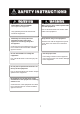
SAFETY INSTRUCTIONS WARNING ELECTRICAL SHOCK HAZARD Do not open the equipment. Only qualified personnel should work inside the equipment. Immediately turn off the power at the switchboard if water leaks into the equipment or something is dropped in the equipment. Continued use of the equipment can cause fire or electrical shock. Contact a ONWA agent for service. Do not disassemble or modify the equipment. Fire, electrical shock or serious injury can result.
TABLE OF CONTENTS INTRODUCTION 2.15 Alarms 2.16 White Marker 2-12 2-14 PRINCIPLE OF OPERATION SYSTEM CONFIGURATION 1. CONTROLS, INDICATIONS 1.1 Control Description 1.2 Indications 2. BASIC OPERATION 2.1 Turning the Power On/Off 2.2 Adjusting Brilliance 2.3 Display mode Selection, Description 2.4 Adjusting Gain 2.5 Automatic Operation 2.6 Selecting Picture Advance Speed 2.7 Display Range selection 2.8 Erasing Weak Echoes 2.9 Measuring Depth to a Fish School 2.10 A-scope Display 2.11 Menu Operation 2.
INTRODUCTION Congratulations on your choice of the ONWA KF-667 Color Video Sounder. We are confident that you will enjoy many years of operation with this fine piece of equipment. The KF-667 is just one of the many ONWA developments in the field of echo sounding. The compact, lightweight but rugged unit is easy to install and operate and is suitable for both fresh and saltwater applications. This unit is designed and constructed to withstand the rigors of the marine environment.
Alarms: fish, bottom, water temperature (requires appropriate sensor). Six pulse lengths for excellent performance on both shallow and deep ranges. Universal 12-24 VDC power supply drawing 30 W of power at maximum. Water temperature sensor optionally available.
PRINCIPLE OF OPERATION This Color Video Sounder determines the distance between its transducer and underwater objects such as fish, lake bottom or seabed and displays the results on a 5.6-inch color screen. It does this by utilizing the fact that an ultrasonic wave transmitted through water travels at a nearly constant speed of 4800 feet (1500 meters) per second. When a sound wave strikes an underwater object such as fish or sea bottom, part of the sound wave is reflected back toward the source.
SYSTEM CONFIGURATION DISPLAY UNIT KF-667 Ship’s mains 12-24 VDC TRANSDUCER External equipment (GPS navigator, etc.
Transducer TX GND TX TD/Temp Temp GND Temp in TX GND TX NC NC GND Fuse(3A) Power DC12-24V -VE I/O NMEA-0183 input(RX+) NMEA-0183 input(RX ) NMEA-0183 output(TX+) NMEA-0183 output(TX ) GND 3.
1. CONTROLS, INDICATIONS 1.1 Control Description The equipment is so designed that even a first time user can quickly become acquainted with the operating procedure. Operation of each control or key is acknowledged by an alphanumeric message or symbol indication on the screen. Control SHIFT-,SHIFT+ (Appears in text as [-],[+].) Function Change display start depth. Select options on menus. ADVANCE (BRILL+AUTO) Pressing the BRILL and AUTO keys together selects display advancement speed.
Change display start depth. Select options on menus. Adjusts brilliance of display. Pressing the SIG LEV + ALARM keys together. Displays the A-scope display at the right 1/4 of the screen. Pressing the BRILL + AUTO keys together. Selects display advancement speed. BRILL AUTO SIG LEV ALARM Eliminates low intensity echoes (up to light-blue echoes) in two steps. Turns the automatic sounder adjustment feature on/off. Open/closes the alarm menu. Shift the Variable Range Marker (VRM). Set alarm zone.
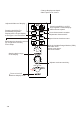
1.2 Indications Auto Mode Mode Noise Limiter Picture Advance Speed Signal Level Nav data* Speed* Water temperature Voltage Water temperature scale* Water temperature marker*(Color changes with HUE setting.) Range scale Alarm zone marker Variable range marker(green) w/depth readout Color bar All indications and markers are displayed in white unless noted otherwise. Depth Requires external equipment.
2.BASIC OPERATION 2.1 Turning the Power On/Off Turn the [MODE] switch clockwise to turn the power on. The unit starts with the settings used before it was turned off last time. To turn the power off, turn the switch fully counterclockwise. 2.2 Adjusting Brilliance Use the [BRILL] key to adjust the brilliance. The selected brilliance level is shown on the display as below. There are six levels of brilliance including off. BRILL:0 2.3 Display Mode Selection, Description 2.3.
2.3.2 Display mode description 200K, 50K (high frequency, low frequency) mode The sounder uses ultrasonic pulses to detect bottom conditions. The lower the frequency of the pulse the wider the detection area. Therefore, the 50KHz frequency is useful for general detection and judging bottom conditions, while the 200KHz frequency is useful for detailed observation of fish schools.
ZOOM mode (high or low frequency) Three types of zoom displays are available: marker zoom, bottom-lock expansion, bottom zoom. The zoom mode to be used can be selected on the main menu with ZOOM MODE. Normal display Variable range marker(green) This section is zoomed This mode expands selected area of the normal picture to full vertical size of the screen on the left-half window. You may specify the portion to expand with the VRM (Variable Range Marker), which you can shift with [ ]or [ ].
2.4 Adjusting Gain The [GAIN] control adjusts the sensitivity of the receiver. Adjust it so that a slight amount of noise remains on the screen. Generally, use a higher gain setting for greater depths and a lower setting for shallower waters. Note: The [GAIN] control is inoperative when the automatic mode is active. Gain too high Gain proper Gain too low 2.5 Automatic Operation Automatic operation is useful when you are preoccupied with other tasks and do not have time to adjust the display. 2.5.
2.6 Selecting Picture Advance Speed The picture advance speed determines how quickly the vertical scan lines run across the screen. When selecting a picture advance speed, keep in mind that a fast advance speed will expand the size of the fish school horizontally on the screen and a slow advance speed will contract it. 1.Press the [BRILL] and [AUTO] keys together. The display should look something like the one below. The fraction shown on the display denotes number of scan lines produced per transmission.
Operate the [RANGE] switch and the display shown below appears. Adjust the [RANGE] control again to select a basic range. RANGE: 30 Note:The [RANGE] switch is inoperative when the auto function is active. 2.7.2 Range shifting The basic range may be shifted up or down with the [SHIFT] keys ([+],[-]). Press a [SHIFT] key and the display shown below appears. Press a [SHIFT] key again to select the amount of shift. SHIFT: 0 Note 1: The maximum shift range is 1000 feet (300 m).
2.9 Measuring Depth to a Fish School The VRM (Variable Range Marker) functions to measure the depth to fish schools or other echo. 1.Press[ ]or[ ]to place the VRM on an echo. 2.Read the VRM range just above the VRM. 2.10 A-scope Display This display shows echoes at each transmission with amplitudes and tone proportional to their intensities, on the right 1/4 of the screen. It is useful for estimating the kind of fish school and bottom composition.
2.11 Menu Operation The menu, consisting of the main menu and system menus, contains less often used functions which do not require frequent adjustment. 2.11.1 Menu selection 1.Set the [MODE] switch in the MENU1 position. NOISE LIMITER OFF 1 2 3 HUE SELECTION 1 (1 - 7) GAIN ADJUST 200KHz 0 (-20 - +20) GAIN ADJUST 50KHz 0 (-20 - +20) CLUTTER LEVEL 0* (0 - 3) ZOOM MODE (B.LOCK) M/Z B/L B/Z MARKER (VRM) VRM WHT / :TO SELECT ITEM -/+:TO SET CONDITION 2-8 *A shown when auto mode in active.
2.Set the [MODE] switch in the MENU2 position. 3. To go to page 2 of the system menu, select B/L RANGE with [ ] and press [ ] again. SYSTEM MENU SYSTEM MENU DEPTH : m ft fa PB ZOOM MARK : OFF ON F/A LEVEL: WEAK MED STRG RANGE1: 15 RANGE2: 30 RANGE3: 60 RANGE4: 120 RANGE5: 200 RANGE6: 400 RANGE7: 600 RANGE8: 1000 ZOOM RANGE: 2 3 B/L RANGE: 10 20 SPEED : kt TEMP : MPH KPH / :TO SELECT ITEM. -/+:TO SET CONDITION. 4 5 / :TO SELECT ITEM -/+:TO SET CONDITION 4.Press[ ]or[ ]to select menu item. 5.
2.11.3 System menu description Menu item Description System Menu DEPTH ZOOM MARK Turns zoom range and expansion range markers on/off. F/A LEVEL Sets fish alarm level. WEAK: Alarm against weak to strong echoes. MED: Alarm against medium to strong echoes. STRG: Alarm against strong echoes only. RANGE 1-8 Sets basic ranges. Change when default ranges are not satisfactory. ZOOM RANGE B/L RANGE 2-10 Selects unit of depth measurement; meters, feet, fathoms, passi/braza.
2.12 Suppressing Interference Interference from other acoustic equipment operating nearby or other electronic equipment on your boat may show itself on the display as shown below. To suppress interference, do the following: 1.Select MENU1 with the [MODE ]switch. 2.Select NOISE LIMITER. 3.Press [+] or [-] to select degree of suppression desired. 3 provides the highest degree of suppression.
2.14 Selecting Background and Echo Colors 1.Select MENU1 with the [MODE] switch. 2.Select HUE SELECTION. 3.Press [+] or [-] to select hue arrangement desired, referring to the table below. Hue options Hue Ho. Background color Echo color 1 Blue 7 colors, bottom reddish-brown 2 Blue 6 colors, bottom red 3 Black 7 colors, bottom reddish-brown 4 Black 6 colors, bottom red 5 White 7 colors, bottom reddish-brown 6 White 6 colors, bottom red 7 Black Monochrome yellow, 8 intensities 2.
2.15.2 Activating/deactivating an alarm 1.Prees the [ALARM] key to display the alarm menu. BOTTOM ALARM ZONE: RANGE: 0 --- ON 5 5 FISH ALARM ZONE: RANGE: OFF 0 --- ON 5 5 TEMP ALARM ZONE: RANGE OFF 32 IN --- / -/+ OUT 37 5 TO SELECT ITEM. TO SET CONDITION. 2.Press [ ] or [ ] to select an alarm . 3.Press [+]to select ON, IN or OUT.
2.16 White Marker The white marker functions to display a particular echo color in white. For example, you may want to display the bottom echo (reddish-brown) in white to discriminate fish echoes near the bottom. Note that the bottom must be displayed in reddish-brown for the white marker to function. 1.Set the [MODE] switch in the MENU1 position. 2.Press [ ] select MARKER field. 3.Select WHT from the MARKER field. 4.Set the [MODE] switch in desired mode position. 5.
3. INTERPRETING THE DISPLAY 3.1 Zero Line Zero line The zero line (sometimes referred to as the transmission line) represents the transducer`s position, and moves off the screen when a deep phased range is used. Shift 3.2 Fish School Echoes Fish school echoes will generally be plotted between the zero line and the bottom. Usually the fish school/fish echo is weaker than the bottom echo because its reflection property is Size of much smaller compared to the bottom.
3.4 Surface Noise/Aeration When the waters are rough or the boat passes over a wake, surface noise may appear near the zero line. As surface turbulence is acoustically equivalent to running into a brick wall, the bottom echo will be displayed intermittently. Similar noise sometimes appears when a water temperature difference (thermocline) exists. Different species of fish tend to prefer different temperature zones, so the thermocline may be useful to help identify target fish.
4. MAINTENANCE,TROUBLESHOOTING WARNING ELECTRICAL SHOCK HAZARD Do not open the equipment. Only qualified personnel should work inside the equipment. 4.1 Maintenance Regular maintenance is important for good performance. Following the recommended maintenance procedures will help keep your set in good working condition. 4.1.1 General checking Important points to be checked from time to time are tabulated below.
4.1.3 Cleaning Keep the equipment clean and dry at all times. Dust or loose dirt should be wiped off with a soft, dry cloth. Do not use chemical cleaners to clean the display unit-they can remove paint or markings. 4.1.4 Maintenance of the transducer Marine life on the transducer face will result in gradual decrease in the sensitivity. Check the transducer face for cleanliness each time the boat is hauled out of the water. Carefully remove any marine life with a piece of wood or fine sandpaper.
4.2 Basic Troubleshooting The troubleshooting table below presents common problems and the means to restore normal operation. If normal operation cannot be restored do not attempt to check inside the equipment. Basic troubleshooting If Then Neither echo nor fixed range scale appears check battery voltage. check fuse. check battery terminal for corrosion. check that power cable is securely plugged. No echo but range scale shows check if display speed is set to"0".
4.3 Transducer Check A simple and reliable check of the transducer is to temporarily replace the transducer with a new one. If the sensitivity is considerably improved through this change, the transducer is probably faulty. This method is especially useful for inside-hull or through-hull installation. Another method is to listen to the transmission sound. Haul the transducer from the water and turn on the power. Put your ear near the transducer face and carefully listen to the transmission sound.
MENU TREE MENU1 MENU2 SYSTEM MENU NOISE LIMITER OFF 1 2 3 HUE SELECTION 1 (1 - 7) GAIN ADJUST 200KHz 0 (-20 - +20) GAIN ADJUST 50KHz 0 (-20 - +20) CLUTTER LEVEL 0* (0 - 3) ZOOM MODE (B.
SPECIFICATIONS ON COLOR VIDEO SOUNDER KF-667 1.GENERAL 1 Display 2 Echo Color 3 4 5 6 7 8 9 10 11 12 5.6-inch TFT LCD 8 colors (including background color) according to echo intensity. Monochrome display is also available. The background color is selectable from blue, light blue, white and black. Basic Range Meters 5/10/20/40/80/150/200/300 Feet 15/30/60/120/200/400/600/1000 Fathoms 3/5/10/20/40/80/100/150 Passi/Braza 3/5/10/30/50/100/150/200 The basic ranges can be changed on the system menu.
2.POWER SUPPLY 1 Display Unit 12-24 VDC -10%,+30% : 1.0 - 0.6 A 3.ENVIRONMENTAL CONDITION 1 Ambient Temperature 0 to +50 2 Relative Humidity 85% at 40 3 Water proofing Display Unit:IPX4 4 Vibration 1mm 10%, 2(5) to 13.2Hz, Maximum acceleration 7 m/s 2, 13.2 to 100Hz 4.COATING COLOR 1 Display Unit Chassis: 2.5GY5/1.5 Panel: N3.0 Newtone No.
INDEX Aeration Alarms activating bottom fish silencing buzzer water temperature A-scope display AUTO key Automatic operation Background color Bottom alarm Bottom echoes Bottom zoom mode Bottom-lock mode BRILL key Brilliance Checking Cleaning Clutter Depth measurement Display mode dual frequency mode Echo color Fish alarm Fish school echoes Fuse replacement GAIN control 200K, 50K mode Hue 3-2 2-13 2-12 2-12 2-13 2-12 2-7 2-4 2-4 2-12 2-12 3-1 2-3 2-3 2-1 2-1 4-1 4-2 2-11 2-7 2-1 2-2 2-12 2-12 3-1 4-1 2-4 2-