
Datasheet

DS.DMSW.MODBUS.ENG.12.05.23.AN
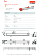
56
13
12
20
28
22
7
18°
40
15,5
42
31,7
28
25
M5
G02
M12 Male Connector
Ordering Procedure
Cursor
Connection
Connecting brackets
BR02
Model Measurement stroke Protocol
DMSW 100 - 5000 mm
DMSW
150
Cursor
103/47
Dead zone
≤ 2000 mm
103/47
> 2000-3000 mm
185/47
> 3000-4000 mm
215/47
> 4000-5000 mm
255/47
1G02: 1 cursor
2G02: 2 cursors
G02
Modbus
MDB:Modbus
BR01
BR02
Baud rade
04
Termination
1S0
1S0: off
1S1: on
01:9600 bits/s
02:19200 bits/s
03:38400 bits/s
04:57600 bits/s
05:115200 bits/s
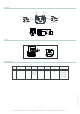
DMSW
M12 Female
A 2
4 B
3 GND
24V+ 5
NC 1
A 2
4 B
3 GND
24V+ 5
NC 1
M12 Female
in out
Error(red)Status(green)
2 / 2
Above given technical data are only for information purpose. OPKON has right to change product specifications without notice.