
Datasheet

Technical Specifications
Type of measurement Magnetic incremental contacless
Measurement stroke 50 - 5000 mm (can be extend up to 50 meters)
Resolution 2,5 / 5 / 10 / 12,5 / 20 / 25 µm resolution (4x mode)
Accuracy
Output channels
± 40 µm
Output type Push-Pull, TTL, Linedriver or High Linedriver
Power supply 5 VDC or 8 -24 VDC
Reference position Optional
Power consumption(without load) < 40 mA (24 VDC)
Electrical connections 2.5 m cable standard, DB9 connector with 1 m cable
Case material Anodized aluminium
Protection level IP 66
Operating temperature
-20°C ... +80°C
-30°C ... +90°C
Storage temperature
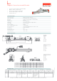
Mechanical Specifications
Ordering Procedure
MLIP
Magnetic Linear Incremental Encoder
DS.MLIP.ENG.16.03.23.AN
Above given technical data are only for information purpose. OPKON has right to change product specifications without notice.
MLIP (mm)
US
(Usefull stroke)
MS
(Mechancal stroke)
L
(Total stroke)
100
100
122
231
50
50
72
181
150
150
172
261
200
200
222
331
250
250
272
381
300
300
322
431
350
350
372
481
400
400
422
531
500
500
522
631
600
600
622
731
700
700
722
831
800
800
822
931
900
900
922
1031
1000
1000
1022
1131
1250
1250
1272
1381
1500
1500
1522
1631
1750
1750
1772
1881
2000
2000
2122
2131
• 2,5 / 5 / 10 / 12,5 / 20 / 25 µm resolution (4x mode)
• Magnetic contactless measurement
• Push-Pull, TTL, Linedriver or HLD output
• Can be used with multiple reader heads
• IP 66 protection level
A,B,Z or A,A, B,B, Z,Z
MLIP
MLIP
Model
T20 LTP
LTP : Push-Pull
TT : TTL
HLD : High Linedriver
LD : Linedriver
Resolution Output type
Pole pitch
500
50 - 5000 mm
(up to 50 m)
Measurement stroke (mm)
2M5
2M5 : 2.5 meter cable
9G : G type electrical connection
9H : H type electrical connection
Connector / Cable
1Z : Ref. at across
the cable side
2Z : Ref. at cable side
3Z : Ref. at middle
5Z : Continues ref.
0Z : Without ref.
B : A,B
Output
T10 : 2.5 µm
T20 : 5 µm
T50 : 12.5 µm
T80 : 20 µm
T100 : 25 µm
B5 B
B5 : 5 mm
B2 : 2 mm
2B5 : 2.56 mm
Power supply
V1
V1 : 5 VDC
V2 : 8 - 24 VDC
Cable output
+V : Brown
0V : Blue
A : Black
B : Whte
Z : Orange
A nv. : Yellow
B nv. : Green
Z nv. : Red
GND : Earth
9G Type Electrcal Connectons
Pn 1 : Ch A
Pn 2 : Ch A nv.
Pn 3 : Ch Z
Pn 4 : Ch B
Pn 5 : Ch B nv.
Pn 6 : Ch Z nv.
Pn 7 : +V
Pn 8 : GND
Pn 9 : Earth
9H Type Electrcal Connectons
Pn 1 : Ch Z
Pn 2 : Ch B
Pn 3 : Ch A
Pn 4 : NC
Pn 5 : GND
Pn 6 : Ch Z nv.
Pn 7 : Ch B nv.
Pn 8 : Ch A nv.
Pn 9 : +V
73
44
M8
24
20
REF. POSITION
MS=US+22
L=US+131
1Z
25
24
140
5°
5°
(±10 mm) Adjustable
M8
63
43
90
50
16
39
45
M8
DB9 male connector
78
21
33
Ø8
M5x20
PIN CONFIGURATION
1
6
5
9