
Manual


- 4 -
- 5 -
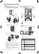
Mount the area viewfinder.
Mounting tips>>
Engagetheconvexsectionoftheareaviewnderxing
arms with the notches of the main unit, and insert and
mount the arms.
Mount the area plate so that an arrow of the plate
center section faces upward and the letter surface can
be seen.
Insert the area plate into the top and bottom grooves of
theareaviewnderuntiltheplateisstoppedbytheribs.
404 (521205)404 (521205)
4010 (521204)4010 (521204)
SIP-3020WF SIP-4010WF
SIP-404WF
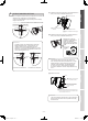
Fine adjust the main unit angle in vertical and horizontal
direction by observing the target area through the area
viewfinder.
•
•
•
(4)
(5)
3 Locate the center circle of the area
plate on the center circle of the lens
oftheareaviewnder,andcheckthe
detection area pattern on the area
plate and the background image.
* Each letter on the area plate
corresponds to each mirror number
(see Step 8-2).
* You cannot observe mirror
numbers B1 to F1 and B6 to F6
(shown at right) of the SIP-3020
area plate through the inspection
window. Check them using the
walk tester.
Adjusting tips>>
Ifyouexperienceanyofthefollowing,seeStep10.
Cautions>>
Theareaviewnderisasupportingtoolfordetectionarea
adjustment.
After you have adjusted the detection area using the area
viewnder,alwayschecktheareausingthewalktester.
Never look directly into the sun through the area
viewnder.
Afteryouhaveusedtheareaviewnder,storeitawayfrom
direct sunlight.
Securely tighten the adjustment screw that you have
loosened.
Connect the walk tester OPM-WT (optional) to the sensor
unit, and check that the detection area is correct.
REDWAVE
REDWAVE
MICROWAVE
REDWAVE
ALARM OUTPUT
CELL BATTERY
POWER
SUPPLY
FROM
SENSOR
POWER OFF
REDWAVE
PIR NEAR
REDWAVE
PIR FAR
MEGARED
FAR
MEGARED
NEAR
REDWALL
REDWIDE
WALKTESTER
REDWALL
REDWIDE
MEGARED
CONNECTION
SELECT
SWITCH
MODE
SELECT
SWITCH
POWER
SELECT
SWITCH
OPM-WT
1 Whenthepowerselectorswitchisturnedto“CELL
BATTERY” position after plugging the cable into the
walk tester connector, a continuous beeping sound will
be heard.
2 When a pedestrian first enters the detection area, the
strong and weak beeps will sound alternately.
3 When the entirety of a pedestrian’s body is detected, the
strong beep will sound continuously.
Cautions>>
OPM-WTcannotbeoperatedatthe“Powersupply
from sensor” position of the power select switch.
•
•
•
•
•
(6)
(7)
Area plate
(an accessory)
Determine the
detection direction
(see Step 5-1).
Put the red string
round the main unit.
Insert and
mount to
the main
unit.
Red string to
hold the main unit
Center circle
of the lens
AreaviewnderAVF-1(optional)
Inspection window
Insert the area
plate into the slot.
Fixingarms
Notch
Convex
section
Grooves
Ribs
Arrow
marking
1 To change the direction of the inspection
window,rotatetheareaviewnderina
horizontal direction until it clicks and stops.
2Moveyourfaceclosetotheviewnder
so that your eye comes within 5 mm of
the inspection window (lens surface).
Center circle of the lens
Center circle of the
area plate
The detection area is
inside the frame
border.
Invisible area
Thesensorareaisextended
over the street where a person
walks or a car drives.
Branches of a tree and grass
move when the wind blows.
* Peel off the
protection
seal from both
faces of the
area plate.
1
2
3
4
Limit line of
detection area
For near area alarm output
For far area alarm output
Useat“REDWAVEALARM
OUTPUT” position to
conrmentireareaalarm
output.
Power selector
switch
Useat“REDWALL”
position.
CELL BATTERY
REDWALL-V_SP-WF_EN.indd 4 2009/05/19 15:48:35