
Installation Manual


-1-
INSTALLATION INSTRUCTIONS
No.59-1881-3 131115UL
No.59-1881-3
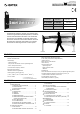
PHOTOELECTRIC DETECTOR
• Quad high power beams
• Double modulated beam
• Smart design
- Slim body design
- Easy-to-see vivid interior color for optical alignment
- IP65*
1
waterproof structure
• 4 channel beam frequency selector
• Alignment level indicator
• Viewfinder with 2X magnification
• Various options (refer to page 20)
( HU-3*
1
, ABC-4*
1
, BC-4*
1
, CBR-4, PSC-4*
1
, BAU-4*
1
)
• UL/c-UL Listed
• Beam interruption adjustment function
• D.Q. circuit (environmental disqualification)
• Tamper function
• Beam power control selector
• Alarm memory
• Sound assist function
-
Optical alignment
- Beam reception status
- Walk test
[ SL-QDM only ]
• Auto Transmit Power Control (A.T.P.C*
2
) to optimize the beam power
• Integrated Alignment Status Communication (I.A.S.C*
2
) to
communicate the transmitter and receiver
• Re-transmitting circuit function
• Solar Battery Unit SBU-4*
1
(option)
PHOTOELECTRIC DETECTOR
A photoelectric detector consists of an infrared light
source that generates IR(Infrared) beams, and an IR
receiver that detects the IR beams. The transmitter
and receiver are installed on opposite sides of the
area to be monitored. The receiver detects when the
IR beams are physically interrupted by an intruder,
and sends an alarm signal to be a control panel.
FEATURES
INTRODUCTION
1-1 BEFORE YOUR OPERATION ....................... 2
1-2 PRECAUTIONS
.......................................................
2
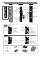
1-3 PARTS IDENTIFICATION
.....................................
3
INSTALLATION
2-1 SEPARATING.................................................4
2-2 WIRING..........................................................4
2-3 TERMINAL ..................................................... 5
2-4 WIRING DIAGRAM ........................................ 5
2-5 WIRING DISTANCE BETWEEN POWER
SUPPLY AND DETECTOR ............................ 6
2-6 WALL MOUNTING ......................................... 6
2-7 POLE MOUNTING ......................................... 8
2-8 MOUNTING IN THE BEAM TOWER.............. 9
2-9
INSTALLATION EXAMPLE AT PARTICULAR CASE
... 9
FUNCTION SETTING
3-1 DIP SWITCH ................................................. 10
3-2 BEAM POWER CONTROL SELECTOR....... 10
1
2
3
4
6
7
8
9
CONTENTS
3-3 FUNCTION.................................................... 11
OPTICAL ALIGNMENT
4-1 OPTICAL ALIGNMENT FOR UPPER AND
LOWER BEAM.............................................. 15
4-2 OPERATION CHECK.................................... 17
TROUBLESHOOTING
5-1 TROUBLESHOOTING .................................. 17
OPTIONAL SETTING
6-1 HEATER UNIT HU-3 (OPTION) .................... 18
6-2 SOLAR BATTERY UNIT SBU-4 (OPTION)... 18
DIMENSIONS
7-1 DIMENSIONS ............................................... 19
SPECIFICATIONS
8-1 SPECIFICATIONS......................................... 19
OPTIONS
9-1 OPTIONS ...................................................... 20
Detection range
SL-200QDM
SL-350QDM
SL-650QDM
SL-200QDP
SL-350QDP
SL-650QDP
Advanced Standard
5
Transmitter
Receiver
Smart Line series
Smart Line series
™
™
60m/200ft.
100m/350ft.
200m/650ft.
*1 not evaluated by UL
*2 not require any additional tool