
Installation Manual


-11-
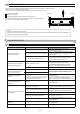
Caution
3-3
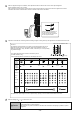
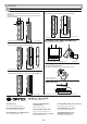
FUNCTION
ON
1 2 3 4 5 6 7
ON
1 2 3
Transmitter
Transmitter A
Transmitter B
Receiver A
Receiver B
1
3
1
3
1
3
1
3
1
3
1
3
2
4
2
4
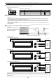
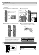
a) Double stacked protection
Since Receiver B may receive the infrared beam from Transmitter
A, select the frequencies as shown in the figure above.
(In the figure, each number in the square indicate a channel numbers.)
Since Receiver C may receive the infrared beam from Transmitter
A, select their frequencies as shown in the figure above.
c) Double stacked long distance protection
Transmitter Receiver
Transmitter Receiver
Receiver Transmitter
Receiver Transmitter
Transmitter Receiver
Transmitter Receiver
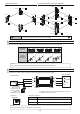
4 CHANNEL BEAM FREQUENCY SELECTOR
1 1
1 1 3 3
Transmitter A Receiver A Receiver B Transmitter B Transmitter C Receiver C
b) Long distance protection
The 4 channel beam frequency selector can be used to avoid unwanted crosstalk that can occur when using multiple photo beams for long
distance or beam stacking applications.
7RVHOHFWEHWZHHQVHSDUDWHEHDPIUHTXHQFLHVXVHWKHVZLWFKSURYLGHG
0RUHWKDQGRXEOHVWDFNHGDSSOLFDWLRQLVQRWSRVVLEOH
SL-QDM
SL-QDP
1
More than double stacked application is not possible.
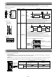
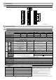
0DNHVXUHWKHUHFHLYHUDQGWUDQVPLWWHUWKDWDUHIDFLQJHDFKRWKHUDUHVHWWRWKHVDPHFKDQQHO
Note>>
ON
ON
ON
ON
Channel 1 Channel 3Channel 2
Channel 4
Receiver
A D
B C
If interference occurs as shown below, use the beam power control selector to reduce beam [A] to less than the specified distance.
Lower the beam power control
selector of transmitter A by one level.
(Refer to 3-2 on page 10.)
Check that the light receiving level
of receiver B is Good or better
without blocking light for both upper
and lower units.