
Installation Manual


-4-
2-1
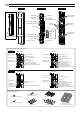
SEPARATING
INSTALLATION
2
1
Remove the cover.
2
1
2
Remove the main unit from the chassis.
Pull the upper part of
main unit, and raise it to
remove.
Turn the optical unit 90 degrees
and loosen the screws (both
sides).
Do not place the main unit where it allows to incident direct sunlight to its optical lens during
installation. Doing so may cause damage to the product.
Caution
3
4
1
2
5
6
2-2
WIRING
1
Cut off the cut bush according to the cable size.
2
5
3
4
1
Preparing the cut bush
Cut the wiring grommet required according to the wire diameter. Use the lidded grommet for the wiring hole not to be used.
(I.D. : Internal diameter)
Refer to "TERMINAL" on Page
5 to make connections to the
terminals and refer to “OPTI-
CAL ALIGNMENT” on Page 15
to make alignment for the
maximum level of light
reception.
Pass the cable through the cut bush.
Connect to the terminalsCut the excess portion of the banding band.Tighten the cable with the banding band.
2
Threading the wire
Do not exceed the voltage or current rating specified for any of the terminals during
installation, doing so may cause fire or damage to the product.
Caution
Pull
Loosen the
cover lock screw.
2
Twist it lightly.
1
3
A coin
(Not included)
I.D. 10mm (0.39 inch)
I.D. 8mm (0.31 inch)
I.D.
6mm (0.24 inc
h
)
I.D. 4mm (0.16 inch)
I.D. 7mm (0.28 inch)
I.D. 6mm (0.24 inch)
I.D. 4mm (0.16 inch)