
Owner manual


Chapter 1 Installation
15
connected to DRY terminal must be separated from power cables. Moreover, these cables should be
double insulated with a typical 0.5 to 1.5 mm
2
cross-section area for a maximum connection length
between 25 and 50 meters.
1.7.1 Dry Contact Interface of Battery and Environmental Temperature Detection
The input dry contact J2 and J3 can detect the temperature of batteries and environment
respectively, which can be used in environment monitoring and battery temperature compensation 1.
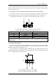
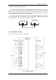
J2 and J3 interfaces diagram are shown in fig 1-13, the description of interface is in table 1-3.
J2 J3
TEMP_BAT
TEMP_ENV
Fig 1-13 Diagram of J2 and J3 dry contact for temperature detecting
Table 1-3 Description of input dry contact interface J2 and J3
Position
Name
Purpose
J2.1
TEMP_BAT
Battery temperature detection
J2.2
GND
Power ground
J3.1
TEMP_ENV
Environment temperature detection
J3.2
GND
Power ground
Note: Specified temperature sensor is required for temperature detection (R25=5Ohm,
B25/50=3275), please confirm with the manufacturer, or contact local maintenance engineers when
placing an order.
1.7.2 Remote EPO Input Port
The UPS has an Emergency Power OFF (EPO) function. This function can be activated by pressing
a button on the control panel of the UPS or through a remote contact provided by the user. The EPO
pushbutton is protected by a hinged plastic cover.
J4 is the input port for remote EPO. It requires shorting NC and +24v during normal operation, and
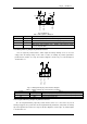
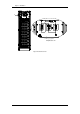
the EPO is triggered when opening NC and +24v, or shorting NO and +24v. The port diagram is shown in
fig 1-14, and port description is shown in table 1-4.
J4
EPO_NC
+24V
EPO_NO
+24V
Fig 1-14 Diagram of input port for remote EPO
Table 1-4 Description of input port for remote EPO