Antenna Extender US 5 Band FCCID: 2AXALAE5BUS00 User Manual Revision: Q Rev Date: 6-14-2021
CONTENTS Instrument Care and Safety Information ................... 1 Product Description .................................................... 1 System Overview ........................................................ 2 Check Package Contents .............................................................. 2 User-Supplied Components ......................................................... 2 Warning and Safety Requirements .............................................. 3 Warning Labels .......................
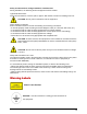
Instrument Care and Safety Information Please read the whole of this section before using your Optical Zonu product. It contains important safety information and will enable you to get the most out of your equipment. Electrical Safety The Optical Zonu Antenna and Equipment Units are Safety Class 1 products (having a metal case that is directly connected to earth via the power supply cable). When operating the equipment note the following: Hazardous voltages exist within the equipment.
System Overview Check Package Contents Before attempting to use this product, please verify the condition of the packaging and it includes all components: • • • • • • • Packing list Antenna Unit (quantity according to PO) Equipment Unit (quantity according to PO) Hybrid Fiber/Power Cable Assembly 48 VDC Antenna Unit Power Supply +12 VDC Equipment Unit Power Supply User Manual Note: If any items are missing or configuration is not as specified, please contact Optical Zonu immediately.
Warning and Safety Requirements Warning. This is NOT a CONSUMER device. It is designed for installation by FCC Licensees and QUALIFIED INSTALLERS. You MUST have an FCC LICENSE or express consent of an FCC Licensee to operate this device. Unauthorized use may result in significant forfeiture penalties, including penalties in excess of $100,000 for each continuing violation.
Safety and Precautions during Installation or Maintenance During installation, the following tools and equipment will be needed. Typical electrician tools Cross-point screwdriver, scissors, pliers, nippers, drill and bits, screws for installing each unit. CAUTION: Do not paint or otherwise coat the equipment. Power Supply Connection Power connection must be carried out following all necessary precautions: • It must be properly made according to the due diligence rules (ex.: EN rules, IEC rules, etc.
System Installation The basic system interconnection is shown in the figure below.
Figure 1. Antenna Extender connections – Antenna Unit Local Power. The Antenna Unit fiber connector is an IP-68 dual LC/APC optical connector. The hybrid cable includes a breakout to the IP-68 rated, Hirose DC connector for the -48VDC. Select the hybrid cable terminated with standard indoor-rated dual LC/APC fiber connectors to connect to 2 riser-rated single mode fibers. The DC conductors are connected to the -48VDC/AC power supply.
Figure 2. Antenna Extender connections - Antenna Unit Remote Power. Select the hybrid cable assembly that makes a home run connection to the Equipment Unit. The -48 VDC power supply for the Antenna Unit is installed here. The -48 VDC Antenna Unit can handle a voltage drop up to 12 VDC. Since the Equipment Unit is installed indoors, a standard indoor dual LC/APC optical cable termination can be used. Using the Senko IP-LCAPC provides additional protection.
Installation Planning The proposed installation must first be analyzed to ensure it will provide the needed coverage. 1. Select a repeater or RF booster that covers the needed frequency band(s) and has a limited maximum RF uplink power. Use a model that has an uplink RF power no more than 24 or 27 dBm. A 10 dB attenuator can be installed in between the repeater and the Antenna Extender Equipment Unit to limit the uplink power to +17 dBm.
Installing the Units The dimensions for Antenna and Equipment Units is shown in the Figure. Figure 4. Antenna and Equipment Unit dimensions in inches. To ensure the maximum downlink sensitivity and maximum uplink transmit RF power, the Antenna Unit should be mounted as close as possible to the donor antenna. Use #12-28 screws (or bolts) with washers to secure the units to a wall or to a strut clamped onto a mast.
Fiber Optic Connections and DC Power The units have no power switch. The unit comes on when DC power is plugged into the unit. The earth ground connections may be connected to either an isolated or common bonding network. Figure 5. Earth Ground Connection. The equipment shall be provided with a suitably listed DC breaker of Fuse in the building installation supply wiring. The DC connections should always be with an isolated DC return.
If the power for the Antenna Unit is to be supplied locally at AC power in a NEMA enclosure, use the hybrid cable that is terminated with the indoor dual LC/APC fiber connectors that can be connected to the pre-installed cable run via a splice tray or patch panel in the NEMA enclosure. The Antenna Unit can also be powered remotely over the hybrid cable run the entire distance to the Equipment Unit.
CAUTION: Use of optical cables with connectors other than as specified will damage the optical connectors on the unit. Always clean the fiber optic cable connectors using standard fiber connector cleaning tools (for example, see https://www.fiberinstrumentsales.com/consumables.html?cat=88) Figure 9. Equipment Unit DC and Fiber Optic Connections. The fiber connector is shown capped.
Specifications Ω 13
Alarms Each unit has a single, multi-color LED with these alarm indications: 1. 2. 3. 4. 5. 6. GREEN - Unit OK RED - Unit Fail SLOW BLINKING RED - Received Optical Power Low / High SOLID YELLOW - Equipment Unit Uplink RF Input low FAST BLINKING YELLOW - Equipment Unit Uplink RF Input High FAST BLINKING RED – Tx Optical Power Out Low / High There are no user accessible electrical alarm connections.
The Minimum Bend Radius of a simplex patch cable is typically 30 mm. Avoid over-bending the cable as this will result in a high optical loss. Connect SC/APC cable to SC/APC modules and FC/APC cable to FC/APC modules only. To connect SC/APC, locate the connector key. Align key and keyway then gently push the plug into the adapter until a click is heard and the connector locks. To disconnect SC/APC just pull back the “square” collar. Replace the dust caps on both the receptacle and the cable plug.
last step clean and dry the end of the ferrule with a dry lint free wipe or surface before insertion. If possible, use a Figure 8 motion and ensure that the tip of the ferrule is always parallel to the cleaning pad. The connectors are all angle-cut. The angle of the angle cut connector is very slight. They have a slope of only about 8 degrees If a dispenser like Cletop is used, push the lever down to expose the cleaning surface. Begin by twisting back and forth and then with the key facing left pull down.
Product Warranty Optical Zonu Corporation guarantees its products and will maintain them for a period of one year from the date of shipment at no cost to the customer. Extended warranty options are available at the time of purchase. Please note that, if a product must be returned to the factory, the customer is responsible for shipping costs.
Troubleshooting No RF Output 1. Verify the correct units are installed at each location a. Donor Antenna Connection – Antenna Unit b. BDA Connection – Equipment Unit 2. Verify Units are properly powered 3. Verify LED Status indicators are GREEN at both units Low RF Output 1. Is the Status LED Blinking RED slowly? – Low received optical power. a. Is the other unit status LED RED or blinking RED fast? i. If yes, that unit has failed. Contact factory for RMA repair. ii. If no, problem is in fiber path b.