
User's Manual

14
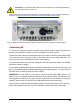
Alarms
Each unit has a single, multi-color LED with these alarm indications:
1. GREEN - Unit OK
2. RED - Unit Fail
3. SLOW BLINKING RED - Received Optical Power Low / High
4. SOLID YELLOW - Equipment Unit Uplink RF Input low
5. FAST BLINKING YELLOW - Equipment Unit Uplink RF Input High
6. FAST BLINKING RED – Tx Optical Power Out Low / High
There are no user accessible electrical alarm connections.
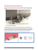
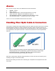
Handling Fiber Optic Cable & Connectors
This product is supplied with angle‐polished connectors (APC) and these must not be confused
with standard flat, spherical or "super" polished connectors. These connector types are not
interchangeable and mating one with the other will damage both the cable and the equipment.
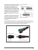
The specification of the optical connector is critical to the performance of the complete fiber
optic link.
Note that a yellow jumper indicates single mode fiber, but the connector end must be green
indicating an angle cut connector (APC).
Ensure that all mating connectors are matched types. All Optical Zonu equipment uses APC
connectors.
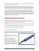
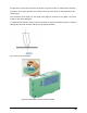
Figure 10. Optical Zonu products use APC (angle polished connectors). These are
always single mode and are indicated by a green boot. Do not try to connect UPC
(ultra-polish connectors – indicated by a blue boot). These are flat polished
connectors that will damage the mating APC connector.