Graphical demo application manual Version LFC24632 for the OPL9724
CAUTION: This preliminary user’s manual may be revised or withdrawn at any time without prior notice. Version User’s manual for the graphical demo application for the OPL9724 Version: LFC24632 May 2003 Copyright 2003, Opticon Sensors Europe BV All rights reserved. Limited warranty and disclaimers By opening the package of this product you agree to become bound by the liability and warranty conditions as described below.
TABLE OF CONTENTS - 3 Table of contents TABLE OF CONTENTS 3 1. KEYS 4 2. 2.1 2.2 2.3 2.4 2.5 2.6 MAIN MENU Scan Labels Scroll data System menu Delete data Send data Version 4 5 6 6 13 14 16 3. DATA FORMAT 17 4. BATTERY 4.1. Battery charging 4.2. Battery near empty 4.3.
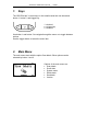
GRAPHICAL DEMO APPLICATION - 1. PAGE 4 Keys The OPL9724 has 3 control keys. In this small manual we use the names button 1, button 2, and trigger key. 1 = button 1 ¤ = trigger key 2 = button 2 Use button 1 and button 2 to navigate through the menu or to toggle between options. Use the trigger button to select the menu item. 2. Main Menu The main menu starts with the option Scan labels. Other options can be selected by button 1 and 2.
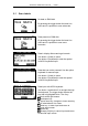
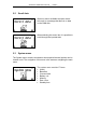
GRAPHICAL DEMO APPLICATION - 2.1 PAGE 5 Scan Labels No data on RAM disk. By pressing the trigger button the laser line emits and it is possible to scan a barcode. Data present on RAM disk. By pressing the trigger button the laser line emits and it is possible to scan more barcodes. Data in display after scanning a barcode. Use button 1 (back) to return. Use button 2 (keyboard) to start the special full ASCII keyboard input. Data that can not be scanned. Use the option keyboard for manual input.
GRAPHICAL DEMO APPLICATION - 2.2 PAGE 6 Scroll data When no data is available the option select will result in a message that there is no data on the RAM disk. When selecting this menu item it is possible to scroll through the inputted data. 2.3 System menu The System menu contains a submenu where special terminal options can be viewed or set. The navigation of this menu is the same as navigating the main menu.
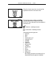
GRAPHICAL DEMO APPLICATION - PAGE 7 When the (back) menu item is selected the application returns to the main menu. The barcode menu enables or disables barcode types that are supported by the OPL9724. More barcodes can be enabled at the same time.
GRAPHICAL DEMO APPLICATION - PAGE 8 With the ‘Communicate’-menu the baudrate and protocol as well as the setup for making a dial-up connection with a remote ISP, a Mailserver and an FTP server can be set. The Interface menu is a multiple layer menu in which the communication method to send data can be selected.
GRAPHICAL DEMO APPLICATION - PAGE 9 The baudrate menu enables or disables one baudrate. Checked = baudrate enabled Unchecked = baudrate disabled By selecting a new baudrate the previous baudrate is disabled. The Dial-up menu can be used to configure the ISP settings for all the communication methods that dial-in on an ISP server using a modem or mobile phone.
GRAPHICAL DEMO APPLICATION - PAGE 10 email address (this address which will appear in the ‘From: ‘ line of the email). The email address needs to correspond with the entered user/name and password of the email account. • Recipients email address This is the email address to which the email will be send. (Address which will appear in the ‘From: ‘ line of the email • IP-address of the SMTP-server The IP-address of the SMTP server of the used email account needs to be entered.
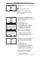
GRAPHICAL DEMO APPLICATION - PAGE 11 The memory menu shows the amount of free memory on the RAM disk. When the message that the RAM disk is (almost) full appears then a small amount of memory is still free. The still available free memory is needed by data communication from the Send data menu. RAM disk is almost full, data is stored. RAM disk is full, data is not stored. The date / time menu item shows the current day, date and time. Use button 1 (BACK) to return to the system menu.
GRAPHICAL DEMO APPLICATION - PAGE 12 Selecting the standby time sets the time the terminal stays on when no key is pressed. When pressing one of the three keys will turn the terminal back on.
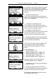
GRAPHICAL DEMO APPLICATION - 2.4 PAGE 13 Delete data When no data is available the option select will result in a message that there is no data on the RAM disk. When selecting this menu item it is possible to delete the inputted data. The default screen when delete data is selected and data is available. This screen will also appear when a successful send data (data transmission) occurs. When cancel is selected the database is not removed from the RAM disk.
GRAPHICAL DEMO APPLICATION - 2.5 PAGE 14 Send data By selecting the ‘Send data’-menu the database, if present, can be transmitted to the device type, protocol and baudrate as set in the communication menu. The Send pictogram that is shown when this menu is selected shows information about the selected communication settings by using different symbols for different settings of the selected communication methods. In the list following all the used symbols are shown.
GRAPHICAL DEMO APPLICATION - PAGE 15 These messages can be: • Place the terminal in the cradle • Place the terminal near the telephone • Place the terminal near the PC • Place terminal in front of IrDA port • Ready to start sending, press a key Besides these setup messages it is also possible that a message will appear which tells you to enter a specific setting before the communication can start, like entering a telephone number, a IP-address or an email address.
GRAPHICAL DEMO APPLICATION - 2.6 PAGE 16 Version Selection the version menu item the current software version is shown. The software version of this application.
GRAPHICAL DEMO APPLICATION - 3. PAGE 17 Data format Each record is stored in a database file called DATA.TXT. The fields in a record are:
GRAPHICAL DEMO APPLICATION - 4. PAGE 18 Battery 4.1. Battery charging If the OPL9724 with the battery pack is placed in the cradle, the voltage and the required loading time is automatically determined. During charging the OPL9724 shows one of the images on the left. Also the RED led on the terminal will emit. When the battery is fully charged the led will be GREEN and the image on the left will be shown. The voltage meter shows the voltage on the contacts of the battery.
GRAPHICAL DEMO APPLICATION - PAGE 19 4.2. Battery near empty During operation a small amount of power is drained from the battery. When the battery detects that the battery is nearly empty, the near empty message is alerted. The OPL9724 can be placed on the cradle to recharge the battery pack or press a key to continue operation. 4.3. Battery empty When already the battery near empty message has been alerted and operation was continued the battery empty message could be alerted.
GRAPHICAL DEMO APPLICATION - Appendix A PAGE 20 The interface Menu In this appendix all the communication methods that can be selected in the interface menu will be described. In the image below all the layers of this menu are displayed with their corresponding menu codes (i.e. 3-3-2-2). On the following pages these menu codes will be used as reference in the descriptions about the communication methods.
GRAPHICAL DEMO APPLICATION - 3-3-2-2 PAGE 21 Making a serial connection with the CRD9723 cradle Before trying to make a connection with the CRD9723 cradle its necessary to check the DIP-switch settings of the cradle to verify if the baudrate settings of the cradle match the selected baudrate in the demonstration program. 3-3-2-2-2 Making a serial connection with a PC Connect the Cradle too the PC by connecting it’s standard serial cable to the serial COM port of the PC.
GRAPHICAL DEMO APPLICATION - PAGE 22 When the modem does not respond to the AT commands, this line can be added to the commands above: AT&D0 Modem doesn’t respond to the DTR signal The cradles of the OPL9723 (cradle type CRD-9723) do not support hardware handshaking. Configure the modem so that it doesn’t use hardware handshaking. The standard 8P8 connector of the serial cable of the CRD9723 cradle is wired as a DCE (Data Communication Equipment).
GRAPHICAL DEMO APPLICATION - PAGE 23 3-3-2-2-3-5 Email the data file the remote mail server using the SMTP protocol The software calls a telephone number of a remote ISP server, using a password and user name of an Internet account. After establishing a connection with the ISP server the software will try to connect to a remote SMTP server, by using its IP-address, the senders-email address and the recipients emails address.
GRAPHICAL DEMO APPLICATION - 3-3-2-3 PAGE 24 Making a bluetooth connection A connection between the OPL9724 and a bluetooth device, like mobile phones or PC's with a bluetooth adapter, can be established by taken the following steps. The first step of setting up a connection between the OPL9724 and the bluetooth device is by making sure the bluetooth device is ‘discoverable’. Otherwise the OPL9724 can’t find the bluetooth device.
GRAPHICAL DEMO APPLICATION - 3-3-2-3-2 PAGE 25 Making a bluetooth connection with a mobile phone To establish a bluetooth connection with a mobile phone, you’ll first need to set up your mobile phone: • Find the bluetooth option in the menu of your mobile phone • Set the bluetooth option to: ON Your mobile phone should now be ready to make a bluetooth connection Before trying to connect to the mobile phone place the OPL9724 near your mobile phone When establishing a bluetooth connection with a mobil
GRAPHICAL DEMO APPLICATION - PAGE 26 3-3-2-3-2-3-2 Sending plain ASCII data to a PC using GSM Before connecting, the remote modem should first be initialized with ‘ATS0=1’modem command so that the modem will automatically go off hook and connects when being called. A serial communication program, like HyperTerminal or Procomm Plus, should be used to be able to initialize the modem and view the received plain ASCII data.
GRAPHICAL DEMO APPLICATION - 3-3-2-3-3 PAGE 27 Making a bluetooth connection with a PC To establish a bluetooth connection with a PC using a virtual bluetooth COM port, you’ll need to set up your PC as follows: • Connect the bluetooth adapter to your PC • Make sure your PC has detected the bluetooth adapter and has installed the correct software, which should have created one or more virtual serial COM ports (i.e.
GRAPHICAL DEMO APPLICATION - 3-3-2-4 PAGE 28 Making an IrDA (infrared) connection Before it is possible to make an IrDA connection make sure the IrDA port of the IrDA device is turned on. Before trying to make an IrDA connection always make sure the IrDA port of the OPL9724 is in line of sight of the IrDA port of the IrDA device.
GRAPHICAL DEMO APPLICATION - PAGE 29 The software calls the telephone number of a remote PC with a modem. The remote PC should be running the program Procomm Plus (Windows or MS-DOS version) in so-called host-mode. The telephone number of the remote PC, the user name and password and the version of Procomm Plus need to be specified before sending. After running the log-in script of Procomm Plus, the Kermit protocol is used to send the data file.