
- OPtima PC


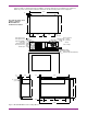


Table Of Contents
- Contents
- 1. Introduction
- 2. Installation
- 2.1 CE EMC Compliance
- 2.2 Mounting
- 2.3 Wiring
- 2.4 Adding Hardware
- 3. Peripheral Devices
- 4. The Operating System
- 4.1 BIOS Password Settings
- 5. Setup
- 5.1 Windows NT Setup
- 5.2 Installing the Wonderware License
- 5.3 Power Shutdown/Battery Backed Power Supply
- 5.4 Backups
- 6. The Display
- 6.1 The Touchscreen
- 7. Keyboard Functionality (Model DSA2 only)
- 7.1 Function Keys
- 7.2 Numeric Keyboard
- 7.3 Left/Right Mouse Buttons
- 7.4 Cursor Keys
- 7.5 Machine Function Keys sent as Keyboard Buttons
- 7.6 Machine Function Keys as Interbus-S Buttons
- 8. Environmental Specifications
- 9. Automatic Logon to Windows NT
- 9.1 Disabling AutoLogon
- 9.2 Bypassing AutoLogon
- 9.3 Changing the Username and Password
- 9.4 Using the Registry Editor
- 10. Troubleshooting/Application Tips
- 11. Disconnecting the Display
- 12. End User License Agreement
- Figures
- Figure 1. Model DSA2 Dimensions for Flange Mount
- Figure 2. Model DSA2 Dimensions for Panel Mount
- Figure 3. Model DSB2 Dimensions for Flange Mount
- Figure 4. External Floppy Drive Cutout and Dimensions
- Figure 5. SA85 Board Jumpers & Switches
- Figure 6. Model DSA2 Keyboard
- Figure 7. Disconnecting the Display
1660-IN-010-0-04 Page 3
5.481
0.075
1.423
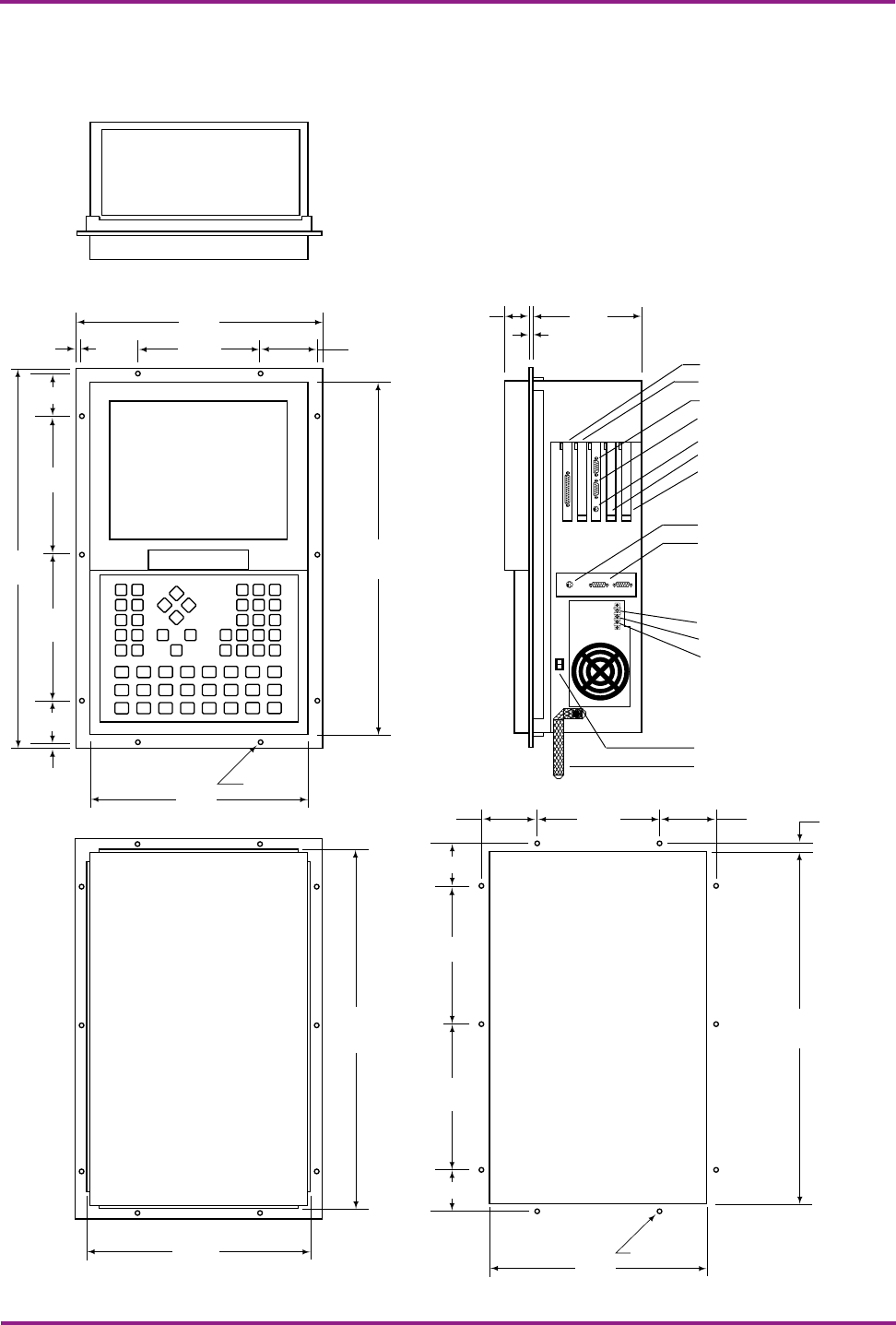
Figure 1. Model DSA2 Dimensions for Flange Mount
Remove cover for access to
expansion slots.
Parallel port
PCI expansion slot
Serial port (COM1)
CRT port
Internal keyboard
ISA expansion slot
ISA expansion slot
External keyboard (mini-DIN)
Interbus-S In (pins)
Interbus-S Out (sockets)
for machine function keys
Chassis Ground
DC - (0 Vdc)
DC + (24 Vdc)
Power Switch
12.620
5.000.375
1.873
7.483
19.462
7.483
1.873
.375
3.435
Ø .218 (10)
17.844
11.000
5.0003.435
1.873
7.483
0.310
7.483
1.873
3.435
Ø .218 (10)
18.092
11.250
17.992
11.150
Bond Strap
24 Vdc
Class 2 Input
Include a switch or circuit breaker in the installation. It must be placed in close proximity to the equipment,
within easy reach of the operator and must be marked as the disconnecting device for the equipment.