
Ultraguard 430 Manual (Rev 7.0)


Manufactures of OptiFUEL™ & OptiPOWER™
Process Measurement & Analysis Ltd
Brook Mills House
Carr Lane
Slaithwaite
West Yorkshire
HD7 5BG
Tel. 0044 (0)1484 843708
Fax. 0044 (0)1484 843689
Email. sales@optifuel.co.uk
WEB. www.optifuel.co.uk
Manual ULTRA Guard 430 - English - Rev 7 - Optional LED 5
Company Registration Number 1015471
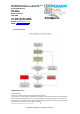
If high intensity LED fitted then board looks like this
High intensity LED indicates that the buffer pack is in use and you should land immediately as BEC or RX
pack has failed.
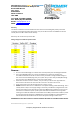
Telemetry
If you use telemetry system on your RX/TX then set low voltage to 0.5V lower than nominal system
voltage. The Ultra Guard 430 sets itself to the nominal system voltage less 0.5 volts during switch on and
arm phase. The unit works on all voltages between 4.8V and 8.4V.
Storage and charging
The Ultra Guard 430 charges whilst in use from the main power pack/BEC and then switched this
function off when charged (charges to 8V & balances). If the unit is not going to be used for some time
remove cable between the Ultra Guard 430 and model. There is a very small current when not in use so
if not going to be used for some time disconnect the buffer pack from board (more than 2-months).
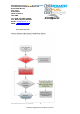
Procedure if LED is purchased as an additional OPTION and not as part of Super Combo.
The LED device can be purchased as an optional add-on to the main board as follows:-
1: The cable that comes with the LED looks like this & can be connected to more than one LED module:-
Plug one end into LED and the other into the socket on the board. Your LED device is now
ready to use. If you intend installing a second LED device to your model the standard cable can
plug into the free port on the first LED and the other end into the second LED.
Optional high intensity LED
indicates the buffer pack is
in use.