
User's Manual


5
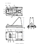
Name Function
2. Power supply LED LED Confirming power supply
2. Indication LED for wired data line Wired data line ( Between PC or Host system and Cradle)
3. Indication LED for wireless data
line
LED confirming connection / disconnection of Bluetooth
4. Terminal for power supply and
Detector
Charging terminal for OPR-3101
5. Charging LED LED confirming charging status of the battery pack
5. Battery charger Battery charger for the single battery pack
7. Scanner detection switch Detecting when the scanner body is put on the battery charger.
8. DC Jack
A jack for charging AC adopter
9. Plug-in phone jack Plug-in phone jack for RS-232C interface
10. USB connector Connector for USB interface
11. Model name label
Shows the names of model, each specification, authentication text, logo and
ID numbers.
12. Dip switch Switch for function settings *Please refer to chart 3 in the next page.
13. BD address label
Scanning it when connecting the scanner and cradle
14. Reserved For other lavel area1.
15. Reserved For other lavel area2.
Chart 2.CHG-3101/CRD-3101 Name of parts and functions