
User's Manual


CRD-3301 SS08xxx
5
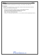
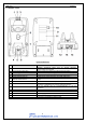
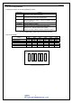
5. Detailed View
Figure1: Detailed view
No.
Items Specifications
1 Wireless communication status LED
Indicates operational status such as whether Bluetooth
communication is connected.
2 Communication status LED LED to indicate the interface and data transmission status.
3 Power Supply Status LED LED to indicate the power supply status
4 Power supply terminal (-) Negative power supply terminal for the scanner (OPR-3301).
5 Power supply terminal (+) Positive power supply terminal for the cradle (OPR-3301).
6 Scanner control terminal
Terminal to transfer the kind of power (AC adapter / USB bus
power).
7 Scanner detection switch Switch to detect if the scanner (OPR-3301) is set on the cradle.
8 Scanner search button
Press the button when the scanner is missing. As long as the
connection is established, the scanner answers via buzzer.
9 Barcode for BD address setting
Scan the barcode with the scanner(OPR-3301) to set the
connection.
10 Dip switch Dip switch for function settings
11 Serial label -
12 DC Jack Power supply jack for the dedicated AC adapter.
13 USB connector USB connector for the USB interface cable.
14 Modular jack
Connector for the RS232C interface cable.