
User Manual

O
RANGE
R610V2
RECEIVER
U
SER
M
ANUAL
F
EATURES
:
• Compatible with DSM2 aircraft radio and module systems
• 6 channel cPPM output allowing for single line connection with compatible devices
• True diversity antennas
• Ultra fast brownout recovery and programmed fail safe mode
• Wide input voltage: 3.7~9.6V
• 6 Channels PWM
• Size: 19.5x30x10mm,
• Weight: 3.7g
Current consumption: 40mA
R
ECEIVER
I
NSTALLATION
The R610V2 incorporates diversity antennas, offering the security of dual path RF redundancy
By orienting these antennas in degree, each antenna is exposed to its own RF environment,
greatly improving path diversity (the ability for the receiver to see the signal in all conditions).
A
NTENNA
P
OLARIZATION
For optimum RF link performance it’s important that the antennas are in an orientation
that allows for the best possible signal reception when the aircraft is in all possible attitudes and
positions. This is known as antenna polarization. The antennas should be oriented perpendicular to
each other; typically vertical and horizontal and at different angles.
R
ECEIVER
I
NSTALLATION IN
A
IRCRAFT
In gas and glow aircraft install the main receiver using the same method you would use to install
a conventional receiver in your aircraft. Typically, wrap the main receiver in protective foam and
fasten it in place using rubber bands or hook and loop straps. Alternately, in electric airplanes
or helicopters, it’s acceptable to use thick double-sided foam tape to fasten the receiver in
place.
B
INDING PROCEDURE
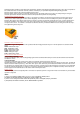
1. Install a bind plug into BIND connector.
2. Apply power to the receiver. It can be from 3.7 to 9.6 volts DC. Please refer to picture on the side of the receiver for the correct pinout
(GND, VCC, SIGNAL)
3. You will see the orange LED rapidly blinking. That means the receiver is in Bind mode.
4. Follow the procedures of your specific transmitter to enter Bind Mode, the system will connect within a few seconds. Once connected,
the orange LED on the receiver will blink several times and go solid indicating the system is connected.
5. Remove the bind plug from the BIND and THRO ports on the receiver before you power off the transmitter and store it in a convenient
place.
After you’ve set up your model, it’s important to rebind the system so the true low throttle and neutral control surface positions are set.
NOTICE:
Remove the bind plug to prevent the system from entering bind mode the next time the power is turned on.
S
MART
F
AILSAFE FEATURE
The R610V2 features advanced failsafe. Advanced FailSafe is ideal for most types of aircraft. With advanced FailSafe, when signal is lost for
the short time (less than 1 second) all channels will hold last command. If the signal loss occurs for more than 1 second all channels go to