
User Manual

ORANGE R620X – R1220X V.2 SERIES RECEIVERS
INSTRUCTION MANUAL
FEATURES:
• Compatible with DSM2/DSMX 1024/2048 aircraft radio and module systems
• cPPM and s.BUS output allowing for single line connection with compatible devices (protocol depends on your model)
• True diversity long antennas that you can place in convenient location in the aircraft
• Ultra fast brownout recovery and programmed fail safe mode
• Wide working voltage: 3.7~9.6V
• 6-12 Channels PWM (depends on your model)
• 9 channels cPPM or 12 channels s.BUS on all receivers (from 6 to 12 channels)
• Integrated telemetry for real time readings:
- Temperature
- Battery voltage
- Receiver voltage
- motor RPM
- Current
If required, integrated telemetry can be disabled during binding procedure.
Range: 2Km LOS (Line Of Site) or more**
Telemetry range – 400m. LOS or more**
Current consumption: 55mA
** Please note: Receiver range highly depends on your transmitter output power, environment conditions (weather, air humidity, obstacles and
metal structures), antenna orientation. Presence of another signal sources (Wifi, FPV etc.) can significantly affect the range and even
completely block reception. These receivers were tested using DSMx transmitter with 18.9dBm(77.62mW) power and a standard 2.4gHz dipole
antenna on it. The range of stable reception was 2km “ground-to-ground”. The range of stable telemetry data was 400m “ground-to-ground”.
Ground-to-Air conditions (LOS) typically give better range than “ground-to-ground”.
RECEIVER INSTALLATION
The R620X – R1220X incorporates diversity antennas, offering the security of dual path RF redundancy
By locating these antennas in slightly different locations in the aircraft, each antenna is exposed to its own RF environment,
greatly improving path diversity (the ability for the receiver to see the signal in all conditions).
ANTENNA POLARIZATION
For optimum RF link performance it’s important that the antennas be mounted in an orientation
that allows for the best possible signal reception when the aircraft is in all possible attitudes and
positions. This is known as antenna polarization. The antennas should be oriented perpendicular to
each other; typically vertical and horizontal and at different angles.
MORE DIVERSITY AND BETTER SIGNAL RECEPTION
For bigger aircrafts, 600 and more size helicopters, gas aircrafts or long range projects you don’t want to give a chance for a signal loss.
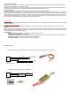
To improve the reception and reduce risks of signal loss you can attach up to two satellite receivers to the main receiver.
Using two additional OrangeRx R110XL 2.4Ghz Satellite Receivers you will get 6(six!!) antennas receiving the signal at the same time.
The antennas should be oriented in different directions and satellites placed at the different sides of the aircraft.
RECEIVER INSTALLATION IN AIRCRAFT
In gas and glow aircraft install the main receiver using the same method you would use to install
a conventional receiver in your aircraft. Typically, wrap the main receiver in protective foam and
fasten it in place using rubber bands or hook and loop straps. Alternately, in electric airplanes
or helicopters, it’s acceptable to use thick double-sided foam tape to fasten the receiver in
place. Mounting receiver antennas and satellites (if used) in slightly different locations,
gives tremendous improvements in path diversity. Essentially, each receiver/satellite sees
a different RF environment and this is key to maintaining a solid RF link, even in aircraft that have
substantial conductive materials (e.g. larger gas engines, carbon fiber, pipes, etc.), which can weaken
the signal.
BINDING PROCEDURE
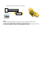
1. Install a bind plug into BIND connector. In case if you want to disable telemetry function on the receiver, install second bind
plug into THRO connector.