ST 9100 Hardware Guide T413, Version 1.
ST 9100 - HARDWARE GUIDE LEGAL NOTICE This documentation is owned by ORBCOMM® and protected by applicable copyright laws and international treaty provisions. Other copyrighted names used are the property of their respective owners. Therefore, you must treat this documentation like any other copyrighted material.
ST 9100 - HARDWARE GUIDE CONTACT INFORMATION Visit ORBCOMM Online www.ORBCOMM.com Contact Customer Support support@skywave.com +1.613.836.2222 Headquarters 395 W Passaic Street, Suite 325 Rochelle Park, NJ 07662 USA Tel: +1-703-433-6300 Fax: 1-703-433-6400 Email: sales@orbcomm.com © ORBCOMM® Proprietary T413, Version 0.
ST 9100 - HARDWARE GUIDE TABLE OF CONTENTS Legal Notice 2 Trademark Notice 2 Export Control Statement 2 Contact Information 3 Contact Customer Support 3 TABLE OF CONTENTS 4 List of Figures 7 List of Tables 7 Preface 8 Purpose 8 Notation 8 Reference 8 Battery Safety Warnings 8 1 Product Overview 10 1.1 Overview of the Messaging System 11 1.2 Terminal 12 1.3 Transceiver Components 12 1.3.1 Transceiver Unit 13 1.3.2 Satellite Antenna 14 1.3.3 Cellular Antenna 14 1.3.
ST 9100 - HARDWARE GUIDE 2.4.1.1 Digital Input 20 2.4.1.2 Digital Output 21 2.4.1.3 Analog Input 22 2.4.2 Dedicated Outputs 23 2.4.3 Multi-purpose Ports 23 2.4.3.1 Input Only Ports 24 2.4.3.2 Analog Inputs (0-5 V) 24 2.4.3.3 Inputs 4-20 mA 25 2.5 Serial Interfaces 25 2.5.1 CAN Bus 25 2.5.2 RS-485/J1708 26 2.5.3 RS-232 (Console and Auxiliary) 26 2.5.4 1-Wire 27 2.6 RF Specifications 27 2.6.1 Satellite (Standard) Antenna 27 2.6.2 Satellite (Low Elevation) Antenna 27 2.6.
ST 9100 - HARDWARE GUIDE 3 Compliance 38 APPENDIX A Development Cable 39 © ORBCOMM® Proprietary T413, Version 0.
ST 9100 - HARDWARE GUIDE LIST OF FIGURES Figure 1: ST 9100 Satellite-Cellular Transceiver 11 Figure 2: System Architecture 12 Figure 3: Connector Position 13 Figure 4: SIM Access Door 13 Figure 5: Reset Button 13 Figure 6: Standard Satellite Antenna 14 Figure 7: Low Elevation Satellite Antenna 14 Figure 8: Cellular Antenna 15 Figure 9: Terminal Shroud 15 Figure 10: Transceiver View of Connector 18 Figure 11: Digital Input 20 Figure 12: Digital Output 21 Figure 13: Analog Input 22
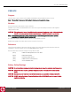
ST 9100 - HARDWARE GUIDE PREFACE Purpose This document is as an overview of the hardware characteristics and specifications for the ST 9100. Note: This is a Beta Trial document. Information in this document is subject to change. Notation A terminal consists of a transceiver unit plus antennas. Hardware components and hardware labels in this document might not be exactly as shown and are subject to change without notice.
ST 9100 - HARDWARE GUIDE CAUTION: DO NOT throw the internal battery or the device into fire. © ORBCOMM® Proprietary T413, Version 0.
ST 9100 - HARDWARE GUIDE 1 PRODUCT OVERVIEW The ST 9100 is a flexible, robust, and programmable dual mode satellite-cellular terminal. It is ideal for remotely monitoring and controlling fixed and portable assets in industries as diverse as transportation, oil and gas, utilities, maritime and more. The versatile, environmentally sealed ST 9100 is ideal for rugged environments in the world’s most remote areas. The ST 9100 (Figure 1) is a satellite-cellular terminal.
ST 9100 - HARDWARE GUIDE Figure 1: ST 9100 Satellite-Cellular Transceiver The transceiver’s built-in programmability allows it to work as a standalone data-messaging transceiver, with built-in I/O data collection and processing capabilities. Feature-rich software tools make programming easy and shorten the design and testing time. The transceiver can also be configured with terminal apps.
ST 9100 - HARDWARE GUIDE Figure 2: System Architecture The satellite-cellular terminal is based on Lua software and is supported by a suite of IsatData Pro tools, enabling SPs a programmable platform they can tailor to their specific applications. 1.2 Terminal Note: Hardware components may not be exactly as shown in this document. A terminal consists of a transceiver unit plus antennas.
ST 9100 - HARDWARE GUIDE 1.3.1 Transceiver Unit Each transceiver is a self-contained unit, including a satellite/cellular modem, a multi-GNSS module, programmable microcontroller, and multiple discrete and analog I/Os (input/output) capable of monitoring and controlling external sensors and devices. Ideal for mobile applications, it is also suitable for fixed installations. Arranging the transceiver unit’s connectors (Figure 3) at one end of the unit simplifies installation.
ST 9100 - HARDWARE GUIDE 1.3.2 Satellite Antenna The satellite-cellular tranceivers’s satellite antenna is waterproof and designed to operate in extreme environments. It has four mounting flanges for installation. The satellite antenna connects to the transceiver using a 5 m (16 foot) cable terminated with a curry yellow colored FAKRA RF connector. The satellite-cellular transceiver is available with either the standard satellite antenna (Figure 6) or the low elevation satellite antenna (Figure 7).
ST 9100 - HARDWARE GUIDE Figure 8: Cellular Antenna 1.3.4 Terminal Shroud Use the optional terminal shroud if mounting the transceiver outdoors. Figure 9: Terminal Shroud 1.3.5 ST 9100 Cables and Connectors The following are available for the ST 9100: l A 5-meter blunt cut cable (p/n ST101062-002). Refer to [T414] for details. l An IP67 Field Installable Connector (p/n ST101096). Refer to [T414] for details. l A development cable (p/n ST101084-001). Refer to APPENDIX A for details.
ST 9100 - HARDWARE GUIDE 2 SPECIFICATIONS 2.1 Temperature Parameter Value Operating Temperature Range -20° to +75°C (-4°F to +167°F) Storage Temperature Range -20° to +60°C (-4°F to +140°F) 2.1.1 Internal Backup Battery Temperature Table 1 defines the internal backup battery's temperature specifications.
ST 9100 - HARDWARE GUIDE Mode of Condition Operation 25°C -40°C (77°F) (-40°F) 85°C Unit (185°F) SatCom Rx Burst current for Rx frequency. 1540045000 1000 2 (C/No=42dBHz) 76.70 25.77 80.13 mA GPS Cold fix current during uBlox on command 32.60 38.37 36.59 mA TOBY Rx (Idle) measure Rx level in 129 channels for 1000 ms intervals 91.52 101.36 102.3 mA measure Rx level in LTE FDD5 for 1000 ms 88.97 92.31 104 mA measure Rx level in LTE FDD 12 for 1000 ms 89.17 91.10 156.
ST 9100 - HARDWARE GUIDE 2.3 Connectors Transceiver 24 position mating connector Chogori Technology Company Satellite Antenna IMS Connector Systems 3400.SMBA.2K10.089 (RG58/LMR-195 sized cable) FAKRA - K-curry yellow Cellular Antenna IMS Connector Systems 3400.SMBA.2D10.029 9RG174 sized cable) FAKRA - D-bordeaux 2.3.1 Connector Pin Assignment Table 3 maps to the layout shown in Figure 10.
ST 9100 - HARDWARE GUIDE PIN Function Type Description 8 Output_6 O Open drain output 9 1Wire Com PWR 1-WIRE return path 10 Console_RS232_TX O ±15 kV ESD protected, RS-232 level (nominally ±5.
ST 9100 - HARDWARE GUIDE Simplified block diagrams of the I/O when configured as digital inputs, digital outputs, and analog inputs are shown in the figures below (Figure 11, Figure 12, and Figure 13). The transceiver also supports two dedicated outputs (Output_5 and Output_6). More information on these outputs can be found in section 2.3.1. 2.4.1.1 Digital Input Figure 11 shows a schematic of the I/O when configured as a digital input.
ST 9100 - HARDWARE GUIDE Parameter Min. Typical Max. Units Input source current with pull-up (Vin = 0.0 V) - 75 - µA Input sink current with pull-down (Vin = 3 to 150 V) - 81 - µA Input bandwidth 1 - - kHz 2.4.1.2 Digital Output Figure 12 shows a schematic of the I/O when configured as a digital output. Figure 12: Digital Output Push-pull S1 = Open Open drain S1 = Closed (Low Impedance) S1 = Open (High Impedance) 2.4.1.2.
ST 9100 - HARDWARE GUIDE 2.4.1.2.2 Switch to Ground Parameter Min. Typical Max. Units Sink current (do not exceed) - - 250 mA Output voltage (sinking 250 mA) I/O_1 to I/O_3 I/O_4 - 1.15 1.40 1.35 1.60 V V Absolute limits (high impedance) -10 - 150 V Output bandwidth 100 - - Hz 2.4.1.3 Analog Input Figure 13 shows a schematic of the I/O when configured as an analog input. Figure 13: Analog Input Parameter Min. Typical Max.
ST 9100 - HARDWARE GUIDE 2.4.2 Dedicated Outputs The transceiver provides two open drain outputs (output_5 and output_6) that can be used to turn on various devices such as relays, lights or audible alarms. These outputs are capable of sinking current only. Both outputs are controlled from the host processor. The outputs are not protected against over current conditions and you must ensure that the maximum current capability of the internal switch is not exceeded. Both outputs include ESD protection.
ST 9100 - HARDWARE GUIDE l Two (2) digital inputs and one 4-20 mA input or, l Two (2) 0-5 V analog inputs and one 4-20mA input. 2.4.3.1 Input Only Ports Four ports (PINs 2, 3, 16, and 24) can be configured as dedicated inputs. Each input is ESD protected by a 36 V transient voltage suppressor that clamps the input transient at 58 V. A 15 V Zener ensures the FET maximum gate voltage of 20 V is not exceeded. Figure 15: Dedicated Inputs Parameter Min. Max. Processor Units 1.
ST 9100 - HARDWARE GUIDE Parameter Maximum input high voltage Min. Max. Units - 32 V 40 44.2 V - 58.1 V ESD TVS breakdown voltage TVS clamp voltage 2.4.3.3 Inputs 4-20 mA The ST9100 can monitor two 4-20 mA sensors. Two ports (PINs 16 and 24) can be configured as two dedicated 4-20 mA receivers. Parameter Min. Max. Units Current Loop Operating current range 4 20 mA Load voltage at 4 mA 0.396 0.404 V Load voltage at 20 mA 1.98 2.
ST 9100 - HARDWARE GUIDE Parameter Min. Typical Max. Units Differential Output Voltage (dominant) 1.2 - 3 V Differential Output Voltage (recessive) No Load -0.5 - 0.05 V CANH or CANL -36 - 36 V Human Body Model 1 - ±16 - kV Contact Discharge Model - ±30 - kV ESD Protection 2.5.2 RS-485/J1708 The transceiver provides a half-duplex RS-485 or J1708 interface as an accessory bus and for SCADA interfacing with signaling rates up to 250 kbps.
ST 9100 - HARDWARE GUIDE Parameter Min. Typical Max. Units Human Body Model - ±15 - kV Contact Discharge Model - ±8 - kV ESD Protection 2.5.4 1-Wire The 1-Wire interface allows connection to downstream 1-Wire devices connected on a bus, or to a single button reader. Relative to any attached 1-Wire device, the transceiver behaves as the master. The 1-Wire driver supports 3 or 5 V devices on the bus.
ST 9100 - HARDWARE GUIDE Parameter Value Rx Operating Frequency 1518-1559 MHz Tx Operating Frequency 1626.5-1660.5 MHz, 1668-1675 MHz 2.6.3 Cellular Antenna Parameter Value Network Coverage Global: Cat 4 LTE (B1, B3, B5, B7, B8, B28), UMTS (850, 900, 1900, 2100), Quad-band GSM Americas: Cat 1 LTE (B2, B4, B5, B12), UMTS (850, 900, 1900, 2100), Quad-band GSM Frequency 700/824/960/1710/1880/2170/2600/2700 MHz Impedance 50 Ω VSWR 2.0:1 Gain 2.5 dB Maximum EIRP 700-2700 MHz 2.6.3.
ST 9100 - HARDWARE GUIDE Parameter GPS GLONASS BeiDou Galileo Hot Start 1s 1s 1s 1s Tracking -162 dBm -166 dBm -160 dBm -159 dBm Hot Start -157 dBm -156 dBm -155 dBm -151 dBm Cold Start -148 dBm -145 dBm -143 dBm -138 dBm 2.5 m 4.0 m 3.0 m TBD Sensitivity Accuracy Horizontal Position Velocity 0.05 m/s Heading 0.3 degrees 2.
ST 9100 - HARDWARE GUIDE 2.11 Environmental Parameter Description Vibration The terminal meets all its specifications during exposure to random vehicular vibration levels per SAE J1455, section 4.10.4.2 figures 6, 7, and 8, and MIL-STD-810H, section 514.8, figure 514.8C-1. Mechanical Shock The terminal meets all its specifications after exposure to positive and negative saw tooth shock pulses with peaks of 20 G and durations of 11 ms as specified in MIL-STD-810H, section 516.8, Procedure I, section 2.
ST 9100 - HARDWARE GUIDE Parameter Condition Min. Typ. Max. Units - 1600 1 Hz - 16384 - LSB/g 4g - 8192 - LSB/g 8g - 4096 - LSB/g 16 g - 2048 - LSB/g Sensitivity Temperature Drift 3 V supply - ±0.02 - %/K Zero-g Offset Ta = 25°C (77°F) - ±40 - mg Output Data Rate (ODR) selectable via digital interface 12.5 Sensitivity 2g Zero-g Offset Temperature Drift 3 V supply - ±1 - mg/K Wake up Time from low power or suspended modes - 0.
ST 9100 - HARDWARE GUIDE Type u-blox Toby L280 series LTE Module LTE bands: 1, 3, 5, 7, 8, 28 UMTS bands: 850, 900, 1900, 2100 MHz GSM 850/900/1800/1900 MHz Output Power LTE power Class 3 (23dBm) UMTS/HSDPA/HSUPA power Class 3 (24dBm) GSM/GPRS Power Class: *Class 4 (33 dBm) for GSM/E-GSM band *Class 1 (30 dBm) for DCSPCS band EDGE(8-PSK) Power Class: *Class E2 (27 dBm) for GSM/E-GSM band *Class E2 (26 dBm) for DCS/PCS band Input Power Peak currents of 1.9 A typical, 2.5 A maximum.
ST 9100 - HARDWARE GUIDE Table 6: LED Operation Sensor Indicates whether the transceiver is receiving sensor data, or if paired with a sensor. Cellular Indicates cellular communications status. Satellite Indicates satellite communications status. Power Indicates that the transceiver has external power. 2.16 Mechanical 2.16.1 ST 9100 Parameter Value Mass 465 g (16 oz) Enclosure Material Lexan plastic © ORBCOMM® Proprietary T413, Version 0.
ST 9100 - HARDWARE GUIDE Figure 17: ST 9100 Top View Dimensions Figure 18: ST 9100 Side Connector View Dimensions 2.16.2 Cellular Antenna Parameter Value Mass 55 g (2 oz..) © ORBCOMM® Proprietary T413, Version 0.
ST 9100 - HARDWARE GUIDE Parameter Value Dimensions 129.5 x 22.8 x 7 mm (5 in. x 0.9 x 0.27 in.) Cable length 3 m (10 ft.) Mounting FAKRA straight plug connector Operating Temperature -40°C to 85°C (-40°F to 185°F) 2.16.3 Satellite Antenna Figure 19: Satellite Antenna (standard and low elevation) - Bottom View (mm) 2.16.3.1 Standard Antenna Parameter Value Mass Side entry with 5 m (16 ft.) cable: 360 g (13 oz.
ST 9100 - HARDWARE GUIDE Figure 20: Standard Antenna Height Dimensions (mm) 2.16.3.2 Low Elevation Antenna Parameter Value Mass Side entry with 5 m (16 ft.) cable: 365 g (13 oz.) Enclosure Material Lexan EXL Color Code 8T9D076 (white) Sealing Gasket Material Santoprene ® Figure 21: Low Elevation Antenna Height Dimensions (mm) 2.16.3.3 Terminal Shroud Parameter Value Mass 150 g (2 oz.) Enclosure Material Lexan EXL Color Code 8T9D076 (white) © ORBCOMM® Proprietary T413, Version 0.
ST 9100 - HARDWARE GUIDE Figure 22: Terminal Shroud Dimensions © ORBCOMM® Proprietary T413, Version 0.
ST 9100 - HARDWARE GUIDE 3 COMPLIANCE & CERTIFICATION Inmarsat Type Approval Industry Canada l ICES-003 l RSS-170, Issue 2, Spectrum Management and Telecommunications Policy, Radio Standard l l FCC RSS-102, radiation safety per Safety Code 6 (compliance shown by computation) IC ID: 11881A-ST9100; 11881A-UNNB30; 8595A-TOBYL280 or 8595A-1EHM44NN l CFR 47 Part 25, CFR 47 Part 15 l CONTAINS FCC ID: XGS-ST9100; XGS-UNNB30; XPYTOBYL280 or XPY1EHM44NN Ingress Protection l Cellular antenna: IP65 l
ST 9100 - HARDWARE GUIDE APPENDIX A DEVELOPMENT CABLE The development cable is p/n ST101084-001. Figure 23: Development Cable © ORBCOMM® Proprietary T413, Version 0.
ST 9100 - HARDWARE GUIDE Table 7: Development Cable Connectors Transceiver Connector End A End B End C End D End E PIN 9 - 1Wire Com PIN 10 - RS232 TX PIN 2 PIN 21 - RS232 RX PIN 3 PIN 22 - AUX RS232 TX PIN 2 PIN 13 - CAN 1 Low PIN D PIN 14 - CAN 0 Low PIN J PIN 1 - RS485 A PIN 1 PIN 24 - Dig IN 2 PIN 16 - Dig IN 1 PIN 4 - I/O_4 PIN 5 - I/O_2 PIN 6 _ Ground PIN A and PIN E PIN 7 - VEXT PIN B PIN 5 PIN 5 PIN 5 PIN 2 PIN 1 PIN 8 - Out 6 PIN 18 - I/O_1 PIN 17 - I/O_3 PIN 3 - Dig IN 3
ST 9100 - HARDWARE GUIDE Transceiver Connector End F PIN 9 - 1Wire Com End G End H End I 1Wire Common PIN 10 - RS232 TX PIN 21 - RS232 RX PIN 22 - AUX RS232 TX PIN 13 - CAN 1 Low PIN 14 - CAN 0 Low PIN 1 - RS485 A PIN 24 - Dig IN 2 PIN 8 PIN 16 - Dig IN 1 PIN 7 PIN 4 - I/O_4 PIN 4 PIN 5 - I/O_2 Input 1 PIN 6 _ Ground Ground PIN 2 PIN 7 - VEXT PIN 1 PIN 8 - Out 6 PIN 6 PIN 18 - I/O_1 I/O_1 PIN 17 - I/O_3 PIN 3 PIN 3 - Dig IN 3 PIN 9 PIN 15 - RS485 B PIN 23 - CAN 0 High PIN 12 - C