S I M P L Y A M A Z I N G® Service Manual Table Top Air Cleaner Super Air 5 / Air 6 Model 447628 & 4478801 REV I., Please disregard all earlier versions.
Important Safeguards When using electrical appliances consideration should be given to basic safety precautions including: 1. Read all instructions. 2. Do not immerse appliance, cord or plug in water or other liquid and take care to ensure that the control panel is kept clean and dry. 3. Do not use the appliance if there is any visible damage to the appliance or to the supply cord. 4. Close supervision is necessary when any appliance is used by or near children. 5.
Table of Contents General Description and Operation . . . . . . . . . . . . . . . . . . . . . . . . . . . . . . . . . . . . . . . . . . page 3 Periodic Maintenance and Tune-Up . . . . . . . . . . . . . . . . . . . . . . . . . . . . . . . . . . . . . . . . . . page 4 Trouble Shooting Guide . . . . . . . . . . . . . . . . . . . . . . . . . . . . . . . . . . . . . . . . . . . . . . . . . . . page 5 Parts Removal and Replacement Procedures . . . . . . . . . . . . . . . . . . . . . . . . . . . . . . . . . .
Periodic Maintenance Tune-Up 1. Remove collecting cell and pre/post filters. 2. Wipe down inside of unit with damp cloth. 3. Thoroughly Clean Collecting Cell with Oreck Assail-A-Cell Cleaner. 4. Check for any broken wires in the collecting cell, and ensure wires are securely seated in the plastic spacer at the center of the cell. Check for any bent plates in collecting cell. Replace if damaged. wires plastic spacer plates 5. Thoroughly Clean pre-filter with warm soapy water. 6.
Troubleshooting Guide Warning: The troubleshooting portion of this manual requires that the unit power be “ON” for much of the servicing portion of troubleshooting. When working on the unit under power, use all of the standard precautions in working with any electro-mechanical device that contains line voltage, high voltage, and rotating elements. Failure to follow standard safety procedures can cause electrical shock, personal injury or property damage. Initially: 1. Plug the unit into a proper outlet. 2.
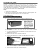
Troubleshooting Guide How to Remove the Power Supply Cover 1. Insert flathead screwdriver into slot on the interior edge of the power supply cover, and push plastic clip away from contact wall so that the cover can be lifted up. Gently pry the plastic clip away from contact wall to release the cover. 2. 3. The switch wires will limit the movement of the power supply cover. Is the switch actuator broken? If the actuator is broken, replace the switch. 4.
Troubleshooting Guide 6. Check the voltage to and from the switch when activated. You should be able to measure line voltage entering and leaving the switch when activated. LINE SIDE LOAD SIDE 7. TO SWITCH, If voltage is present on line side of the switch but not present on load side, the switch is bad. FROM SWITCH, If there is no voltage on line side of the switch, check the wall outlet. If there is voltage at the outlet, then the line cord is bad. Check the switch plate cover.
Troubleshooting Guide c. If the light does not operate with the cell removed, check the wires to the light and confirm that they are properly connected. Check the voltage from the light terminals on the power supply board. Set meter to appropriate scale. You should have about 16 volts DC. If the wire has voltage, the light is bad and needs to be replaced. If the wire does not have voltage, go to next step. d. Option 1: Check the output of the power supply by using the recommended H.V.
Troubleshooting Guide e. Check the input voltage to the transformer using a standard lead and a multimeter. Check the voltage from the black lead on the terminal L speed control switch and white lead on power supply board labeled line neutral. Activate the interlock switch. The meter should indicate line voltage. Check the voltage on the two yellow wires on the power supply board from the transformer. The interlock switch must be activated. The meter must indicate 24 vac.
Troubleshooting Guide d. If there are no signs of distortion, remove the blower wheel (see: Blower Wheel Removal) and activate the unit. Notice if the motor shaft rotates without the blower wheel. If the motor shaft operates, the problem is related to the blower wheel. If the motor shaft rotates then replace the blower wheel drive grommet and bearing wall. If the motor shaft does not rotate, replace the motor. 4.
Troubleshooting Guide c. Check to see if the blower wheel is adequately supported by the outside bearing plate assembly. The outboard end of the blower wheel should be firmly supported, allowing no movement other than rotation. If that end of the wheel can be moved front to back and up and down, remove the bearing plate assembly and check the bearing for damage or excessive wear. Replace parts as needed. Use care in handling the blower wheel. Do not distort the wheel blades.
Troubleshooting Guide 6 If the cell is arcing, check the following: a. If there are loose or broken ionizer wires. Replace the cell. b. If the cell is dirty. Remove the cell and wash with warm soapy water. Dry completely before re-installing. c. If there are bent cell plates. Replace the cell by following instructions on inside of cabinet top. d. If the cell is improperly installed in the unit. Reinstall the cell. e. If the cell contacts are broken or loose. CELL CONTACTS Replace the cell.
Troubleshooting Guide f. If the H.V. contacts are not properly aligned or the contact wall is not properly aligned. The H.V. contacts must make good contact. Replace the contact wall or straighten the contacts, if possible. 7. Checking for ionizing needle operation. Using HV voltage probe check needle for high voltage -5.5 KVDC to -7.0 KVDC. a. If voltage is present, the ionizer is OK. Clean needle with alcohol and a cotton swab. b. If voltage is not present, check HV power supply. See above diagram.
Notes _____________________________________________________________________________ _____________________________________________________________________________ _____________________________________________________________________________ _____________________________________________________________________________ _____________________________________________________________________________ _____________________________________________________________________________ ______________________________________
Super Air 5 Model 447628 Parts Removal and Replacement General Parts Replacement Motor Removal and Replacement page 16 Power Supply Removal and Replacement page 19 Transformer Removal and Replacement page 21 Bearing Wall Assembly and Blower Wheel Removal and Replacement page 22 Led Assembly Removal and Replacement page 23 Cell Assembly Removal and Replacement page 23 Ionizer Needle Removal and Replacement page 23 Fan Blade Removal and Replacement page 24 Warning - All parts remova
General Parts Replacement Motor Removal and Replacement 1. Remove the cabinet top by pressing down the thumb latch and sliding the top forward. 2. Remove the cell assembly (see inside of top for instructions). 3. Remove the stripper by pulling it to the right and applying pressure to the bearing wall. Lift the left hand side of the stripper out of the bearing wall locator seat and then remove the stripper. 4.
General Parts Replacement ROTATING ELEMENT WARNING - Unit has a rotating blower wheel and cooling fan to circulate air and keep the unit cool. When servicing the unit and repairing the unit always insure that you keep objects and internal electrical wiring away from the rotating elements. Failure to allow for proper clearance for rotating members can cause electric shock, personal injury or property damage. 5.
General Parts Replacement HIGH VOLTAGE WARNING - This equipment is supplied with line voltage from a standard wall socket. Use standard precautions in working on it with line voltage applied. Failure to practice normal electrical safety precautions can cause electrical shock, personal injury or property damage. 9.
General Parts Replacement Power Supply Removal and Replacement 1. Follow steps 1, 3, and 6 of Motor Removal and Replacement. EXTREME HIGH VOLTAGE WARNING - This equipment is supplied with line voltage from a standard electrical wall socket. That voltage is transformed to a 24V signal that is then amplified to over 6000VDC. In working with the equipment you must always know the voltage level for the equipment and wiring.
General Parts Replacement All leads must be connected to the new board properly. The HV power line must be isolated and properly routed. Two insulator sheets must be in position and all wiring must be captured to prevent contact with rotating elements. A wiring diagram is included in the service manual for your use. 3. The new board may now be reinstalled in the housing by sliding it back into position. The housing has two board reference ribs molded in the bottom that hold the board in position.
General Parts Replacement 5. To test the power supply, touch the metal shaft of a screwdriver, with an insulated or plastic handle, to one of the contacts while keeping the screwdriver tip about 1/8" away from the other contact. You should see an arc and hear a snapping sound. 6. Reverse step 1. Transformer Removal and Replacement 1. Follow steps 1, 2, 3, and 6 of Motor Removal and Replacement. Remove two #6 screws and nuts that secure the transformer to the cabinet bottom.
General Parts Replacement 3. Remove the two #8/32 lockwasher nuts and remove the transformer and replace it with the new unit. 4. Reverse the above steps 1,2, and 3 to replace the transformer. Bearing Wall Assembly and Blower Wheel Removal and Replacement 1. Follow steps 1, 2, 3, 4 and 5 of Motor Removal and Replacement. 2. The rubber grommet will need to be removed from the motor shaft. This can be done by cutting it off using a sharp razor knife and slitting the grommet along the motor shaft axis.
General Parts Replacement Led Assembly Removal and Replacement 1. Follow steps 1, 2, and 6 of Motor Removal and Replacement. 2. Disconnect the two red led leads from the power supply board and remove the led assembly by removing the led retaining ring from the back of the front panel and removing the led and the leads. LED LEADS 3. Replace with a new led assembly. 4. Reverse the above steps 1 and 2 to replace the led assembly. Cell Assembly Removal and Replacement 1.
General Parts Replacement EXTREME HIGH VOLTAGE WIRING WARNING - The unit has been designed such that extremely high cell collector voltage wiring is isolated from all other wiring. Special wiring routing holders have been designed into the unit. This extremely high voltage wiring must be routed correctly. Failure to route and isolate the wire can create a fire hazard, personal injury or property damage. 2.
Parts List QTY 1 1 1 1 2 1 1 1 1 1 1 1 1 1 1 1 1 1 1 2 1 1 1 1 2 3 1 1 ITEM # 1 2 3 4 5 6 7 8 9 10 11 12 13 14 15 16 17 18 19 20 21 NLA PART NO.
LINE NEW BRN (MED) RED RED (LO) LED RED 1 120V, 60HZ WHT BLACK (RIBBED) BLK 120V 24V WHT POWER SWITCH OUTPUT POS 1 POS 2 POS 3 POS 4 POS 5 OFF L-1 L-1,4 L-2,4 L-3,4 YEL YEL GRN GRN GRN BLUE (242477-035) BLUE (242477-035) POWER BOOST SWITCH BLACK (RIBBED) BLOWER ION./COLL. CELL RED CONTACT WALL BLK (HI) HV POWER SUPPLY POWER SWITCH 2 INTERLOCK SWITCH LED LINE CORD FUSE Wiring Diagram GRN (242477-027) RED (142475-001) ©2004 Oreck Holdings, LLC. All rights reserved.
Notes _____________________________________________________________________________ _____________________________________________________________________________ _____________________________________________________________________________ _____________________________________________________________________________ _____________________________________________________________________________ _____________________________________________________________________________ ______________________________________
©2004 Oreck Holdings, LLC. All rights reserved. All trademarks are owned and used under the authority of Oreck Holdings, LLC.