VERTICAL/HORIZONTAL 22 TON LOG SPLITTER MODEL NO. S402022H0 & S402022K0 Owner’s Manual ASSEMBLY & OPERATING INSTRUCTIONS WARNING: All operators must read this manual before operating this log splitter. Follow the safety instructions in the manual and in decals attached to the product. Failure to do so could result in serious injury or death. LS181-877-0411 Rev.
Table of Contents Important Safety Information................................................................................................................. Page(s) 1-6 Intended Use ......................................................................................................................... 1 Personal Protective Equipment ............................................................................................... 1 Safety Decals .............................
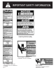
WARNING: Read and thoroughly understand all instructions in this manual and on safety decals before assembling or operating this log splitter. Failure to do so may cause serious injury or death. Do not allow anyone to operate this log splitter who has not read this manual. As with all power equipment, a log splitter can be dangerous if assembled or used improperly. Do not operate this log splitter if you have any questions concerning safe operation.
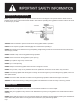
PART NUMBER: S52062400 LOCATION: HYDRAULIC TANK LOWER TANK, RIGHT CORNER PART NUMBER: S52062200 LOCATION: TOP OF CYLINDER PART NUMBER: S52062100 LOCATION: TOP OF HYDRAULIC CYLINDER Page 2 PART NUMBER: LOCATION: OUTSIDE OF BOTH STRIPPER PLATES
GENERAL SAFETY ALWAYS keep the operator’s manual nearby for reference. Reread the manual periodically. ALWAYS establish a safety zone restricting bystanders to a 10 foot radius around the log splitter when log splitter is in operation. ALWAYS ensure that all operators are properly trained or have read and understood the operator’s manual. ALWAYS operate the log splitter with a clear mind, free of the influence of alcohol, drugs or medication.
OPERATION OF THE LOG SPLITTER ONLY operate the log splitter from the operator zone as shown in the diagram. The operator has the safest and most efficient access to the control valve and the beam in this location. Operating the log splitter in another location can result in serious injury or death. TOP VIEW OPERATOR ZONE ALWAYS block the wheels to prevent movement of the log splitter while in operation. KNOW how to stop the log splitter and disengage the controls before operating it.
NEVER perform any service or repair on your log splitter without first removing the spark plug wire. ALWAYS perform all recommended maintenance procedures before using your log splitter. ALWAYS check the level of hydraulic oil and engine oil before operation. ALWAYS periodically check that all nuts, bolts, screws, hydraulic fittings and hose clamps are tight. ALWAYS replace all damaged or worn parts immediately. ALWAYS be sure that all replacement parts meet manufacturer’s specifications.
IMPORTANT NOTE – (spark arrester): As a precautionary measure against possible flying sparks, always take a Class B fire extinguisher with you when operating this log splitter in dry areas. This log splitter is equipped with an internal combustion engine and should not be used on or near any unimproved forest-covered, brush-covered or grass-covered land unless the engine’s exhaust system is equipped with a spark arrester meeting applicable local or state laws (if any).
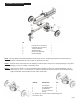
ASSEMBLY INSTRUCTIONS ITEM NO. DECSRIPTION QTY. 1 Road-Speed Tire and Wheel 2 2 Hardware Kit (not shown) 1 3 Tongue Assembly 1 4 Tank Assembly 1 5 Beam Lock Assembly 1 6 Beam Assembly 1 NOTE: This log splitter was partially assembled at the factory. Refer to the drawing and parts list should it become necessary to disassemble the unit for repair or replacement of parts. STEP 1: Remove all the components from the shipping container.Inspect each piece for shipping damage.
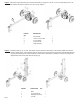
STEP 3: Attach the tongue assembly (5) to the tank assembly (1) using two 1/2” NC x 4-1/2” hex cap bolts (2), two 1/2” lock washers (3) and two and two 1/2” hex nuts (4). Tighten. 5 ITEM NO. QTY. 1 2 3 4 5 DESCRIPTION Tank Assembly 1/2” NC x 4-1/2 Hex Bolt 1/2” Lock Washer 1/2” NC Hex Nut Tongue Assembly 1 2 2 2 1 STEP 4: Stand the beam (1) up on end. Two people may be needed for this step to ensure safety. Make sure that the beam is stable and on a level surface.
STEP 5: Connect the end of the 1/2” ID x 38” hydraulic pressure hose (1) coming from the fitting on the pump to the fitting on the valve. See illustrations below. STEP 6: Slide one hose clamp on the end of the 1/2” x 56” hydraulic return hose (2 ) that comes from the fitting on the filter. Then connect the hose to the fitting on the valve.Tighten hose clamps. See illustrations below. Area of Detail ITEM NO. DESCRPTION QTY.
REPLACEMENT PARTS TANK/ENGINE ASSEMBLY BREAKDOWN ITEM NO. PART NO. DESCRIPTION QTY. 1 O/L 5/16” Flat Washer 8 2 O/L 5/16”-18UNC Nylock Nut 4 3 O/L 5/16” x 1-1/2” GR 5 Bolt 4 4 S40118800 Tank 1 5 S390604B0 Filter Base 1 5A S390601A0 Filter Element 1 6 S39034900 3/4” Hex Nipple 1 7 S39038300 Straight Fitting, 3/4” NPT to 1 3/4” ID Tube 8 S39032000 3/4” NPT x 3/4” Tube 1 9 S39037100 Pump/Honda Engine Assy. or 1 S39074000 Pump/Kohler Engine Assy.
ENGINE/PUMP ASSEMBLY BREAKDOWN ITEM NO. PART NO. DESCRIPTION QTY.
TONGUE ASSEMBLY BREAKDOWN ITEM NO. PART NO. DESCRIPTION QTY. 1 O/L M10 x 1.5 x 120mm GR5 Bolt 2 2 O/L M10 x 1.5 Nylock Nut 2 3 O/L M10 Flat Washer 6 4 S40032300 Chain w/Hook 2 5 S40034600 Hitch Ball Assembly 1 6 S40127400 Ground Stand 1 7 S401215A0 Tongue 1 8 S9114-1 Retaining Ring 1 9 S9132-1 Washer 1 O/L- Obtain locally. Common fasteners available through hardware and farm stores.
OPERATING INSTRUCTIONS WARNING: Read and thoroughly understand all instructions and safety information before operating this log splitter. Failure to do so may cause serious injury or death. Do not allow anyone to operate this log splitter who has not read this manual. As with all power equipment, a log splitter can be dangerous if assembled or used improperly. Do not operate this log splitter if you have doubts or questions concerning safe operation.
To Stop the Engine 1) Move the throttle lever to the SLOW position. 2) Move the throttle lever to the STOP position. 3) Turn the fuel valve to the OFF position. ENGINE OIL RECOMMENDATIONS (Kohler SH265) For temperatures above 32 degrees F use an 10W-30 oil. Using mutigrade oil may increase oil consumption. Using SAE 30W oil below 40 degrees F will resuilt in hard starting and possible engine bore damage.For temperatures below 32 degrees F use an SAE 5W-20 or SAE 5W-30 oil. Oil capacity is about 1.
CAUTION: TURN FUEL SHUT OFF VALVE TO THE “OFF” POSITION PRIOR TO TOWING.FAILURE TO DO SO MAY RESULT IN FLOODING THE ENGINE. NOTE: The engine maximum governed speed is preset at the factory at 3600 RPM no load speed. When splitting wood the throttle should be set at the maximum speed to develop the horsepower required for the pump. OPERATION WARNING: See safety information related to operation of the log splitter in the safety section of this manual.
Log Splitter Accessories Make your log splitter more productive with these optional accessories! S40200600 Log Catcher Bolts onto side of the log splitter beam in minutes. Saves time. Saves your back. Holds the split log off to the side until you are ready to quarter it. No more bending over to pick up half split logs. S40201200 Four Way Wedge Page 16 Double your productivity with this handy attachment. Just slip the 4-way wedge over the standard wedge.
IMPORTANT NOTICE We, the manufacturer, reserve the right to change the product and/or specifications in this manual without notification. The manual is for information usage only and the pictures and drawings depicted herein are for reference only. NOTES Warranty Repair and Service Do not return this product to the store for warranty issues or repair. Call 1-800-525-8322 for the location of the nearest service center. Record the information below for future reference. Model No.
SPECIFICATIONS Engine Pump Cylinder Valve Maximum Splitting Force Honda GC190 or Kohler SH265 Two-Stage, 11 gpm 4 in. Diameter x 24 in. Stroke Auto-Return 22 Tons* Maximum Log Length Cycle Time 26 in. 13 Seconds* Wheels 4.80 x 8 in. Road -Speed Wedge 8 in. High with Spreader WIngs Beam Hydraulic Capacity Filter 6 in. x 9 in. with Built-In Log Cradle 6.5 Gal. Maximum Spin-On Replaceable Height 43 in. in Horizontal Position Length 95 in. Width 49 in. Weight 595 lbs.