INSTALLATION MANUAL Single Station Thermal Printer Model: BTP-2002NP z This printer has been manufactured and branded for ORIENT Technologies B.V. by Shandong New Beiyang Information Technology Co., Ltd. z Design and specifications are subject to change without notice. Ask your supplier for technical specifications before purchase and/or use. z Whenever in doubt about safety issues that might arise from using this product, please contact the supplier immediately for assistance.
BTP-2002NP Installation manual Declarations Changes without notice Information in this document is subject to change without notice. ORIENT Technologies bv (hereinafter referred to as “ORIENT Technologies”) and SHANDONG NEW BEIYANG INFORMATION TECHNOLOGY CO., LTD. (hereinafter referred to as “SNBC”) reserves the right to improve products as new technology, components, software, and firmware become available.
BTP-2002NP Installation manual Contact us In CHINA: Address: Hot line: Fax: E-mail: Website: No.169 Huoju Rd, Weihai, Shandong, China. 264209 +86-631-5673777 +86-631-5673778 sales@newbeiyang.com www.newbeiyang.com (via Contact button) In EUROPE: ORIENT Technologies bv Address: Hot line: Fax: Website: Meerheide 115, 5521 DX Eersel, The Netherlands +31-497-331080 +31-497-386430 www.orient-technologies.
BTP-2002NP Installation manual CONTENT GENERAL SAFETY INFORMATION..................................................... 2 1 PARTS IDENTIFICATIONS ............................................................ 3 2 SETTING UP THE PRINTER ......................................................... 5 2.1 Unpacking ..............................................................................5 2.2 Connecting the Cables..........................................................5 2.2.1 Interface Connector .......
BTP-2002NP Installation manual General Safety Information Before installing and using the printer, please read the following items carefully. Safety Labels Don’t touch the cutter and tear bar of printer. The print head is a thermal element and it is at high temperature during printing or just after operation, therefore please do not touch it and its peripherals for safety reasons. The thermal head is an ESD-sensitive device. To prevent damage, do not touch either its printing part or connecting parts.
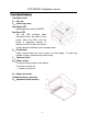
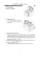
BTP-2002NP Installation manual Parts Identifications 1— Cutter cover 2— Tear bar 3— Printer top cover 4— Power LED Indicating power status (ON/OFF). 5— Error LED The red LED indicates basic information about the status of the printer. When the LED is off, the printer is operating normally. A flashing red LED means the printer needs operator assistance (such as paper end). 6— Feed button Under normal status (no error), press it to feed paper. To feed long lengths of paper, press the key continuously.
BTP-2002NP Installation manual 12-Cutter acting blade 13-Printer platen 14-Cutter fixed blade 15-Paper end sensor For continuous paper, this sensor is used to detect whether the paper roll has run out. 16-Paper-width-adjust module There are 4 long slots at the base of paper holder, putting the paper-width-adjust module in different slot will allow the printer to use different width papers listed as follows:80±0.5 mm, 76±0.5 mm, 69.5± 0.5 mm, 57.5±0.5 mm.
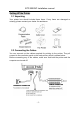
BTP-2002NP Installation manual Setting UP the Printer 2.1 Unpacking Your printer box should include these items. If any items are damaged or missing, please contact your dealer for assistance. 2.2 Connecting the Cables You can connect up the cables required for printing to the printer. They all connect to the connector panel on the back printer, which is shown below: Before connecting any of the cables, make sure that both the printer and the computer are turned off.
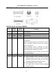
BTP-2002NP Installation manual 2.2.1 Interface Connector RS-232 serial interface (DB25F) Pin Signal name Signal direction Function 1 FG — Frame ground 2 TXD Output Transmit data 3 RXD Input Receive data 4 RTS Output 6 DSR Input Same as DTR signal This signal indicates whether the host computer can receive data. SPACE indicates that the host computer can receive data, and MARK indicates that the host computer cannot receive data.
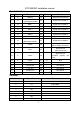
BTP-2002NP Installation manual Parallel interface Pin Source Function Pin 1 H NStrobe 19 Signal Ground (nStrobe) 2 H 20 Signal Ground (Data 1) 3 H Data 1 21 Signal Ground (Data 2) 4 H Data 2 22 Signal Ground (Data 3) 5 H Data 3 23 Signal Ground (Data 4) 6 H Data 4 24 Signal Ground (Data 5) 7 H Data 5 25 Signal Ground (Data 6) 8 H Data 6 26 Signal Ground (Data 7) 27 Signal Ground (Data 8) Data 0 (Least Significant Bit) Data 7 9 H 10 P NAck 28 11 P Busy
BTP-2002NP Installation manual USB interface Pin Number Signal Name 1 VBUS Function +5V 2 DATA- Printer data transmit line minus 3 DATA+ Printer data transmit line plus 4 GND Ground 2.2.2 Cash Drawer Connector The drawer kick-out drive pulses are generated by command. The host can retrieve the status of the drawer by using the DLE EOT, GS a, or GS r commands.
BTP-2002NP Installation manual Caution: Adjust the paper width by adjusting the paper-width-adjust module according to the paper type used. Make sure that the paper roll is cut according to the requirement below before loading: Make sure that the heat sensitive side of paper faces the print head and the rolling direction of paper meets the requirements. The paper roll should be kept from being loose. Or it may cause paper jam or other malfunction.
BTP-2002NP Installation manual 5) Tear off the surplus portion of paper by using the tear bar. Caution: While encountering cutter malfunction due to paper jam or unexpected power loss, do not open the top cover of the printer by force since the moving blade of the cutter might blocked the cover. Failing to do so might damage the moving blade of the cutter. In case the moving blade is blocking the cover of the printer, please follow the instructions below to solve the problem.
BTP-2002NP Installation manual Switch, Button and LED 3.1 Power Switch The power button (a rocker switch) turns the power on or off. Note: Turn the power on only after connecting the power supply. 3.
BTP-2002NP Installation manual the temperature of the print head has increased too much, the printer will decrease its print speed. If the temperature becomes higher than 65℃, the protection circuit of the printer will force the printer to stop printing; at the same time the light and sound signals as described in the table will be given.
BTP-2002NP Installation manual ENQ, and DLE DC4 are not executed. (3) Insufficient print data to fill the last line can be printed by pressing the FEED button. 3) Ending hexadecimal dumping Hexadecimal dump mode can be ended by turning off the power, or press the FEED button three times, or reset the printer after printing has finished. < print sample in Hexadecimal Dump mode > Specifications 6.
BTP-2002NP Installation manual 6.2 Auto Cutter Specifications Item Parameter Remarks Cutter type Slide cutter (Guillotine type) Cutting time 600ms The time that one cut takes. Cutting interval 2s 30 times/min. (Max.) Paper type Thickness: 0.065 – 0.1mm Operation voltage 24VDC Thermal paper or paper with the same thickness Max. static current 1.2A 24V DC Cutter lifetime 1,000,000 cuts (with reference paper) Full cut or Partial cut 6.
BTP-2002NP Installation manual 6.6 Reliability 1) Life times: Thermal head: 100,000,000 pulses, 100 km Auto cutter: 1,000,000 cuts 2) MTBF: 360,000 hours 3) MCBF: 52,000,000 lines 6.7 Black Mark Specifications Printer can work in the mark paper mode, and in accordance with mark to set cutting and the start print location. In addition to mark paper need to meet the specification for Thermal roll, should also meet the following requirements: z L1 Mark height: 5mm≤L1≤10mm. z L2 Mark length: L2≥12mm.
BTP-2002NP Installation manual 6.8 Overall Dimension FEED Button Configuration Parameter setting (configuring) by Feed button 1) Hold the FEED button pressed while switching the printer on. 2) After the printer has printed the configuration sheet, press and hold the FEED button to configure the printer. The main menu for the key-stroke setting procedure is printed. 3) The procedure consists of several sub-menus and step-by-step working is needed. 4) With every choice is a number.
BTP-2002NP Installation manual ¾ Parameter Setting by Feed Button Main Menu Exit Print Self Test Configuration Cutter Test Sensor Test >1 >2 >3 >4 >5 ¾ Setting Configuration of the Printer Configuration Exit Exit with Communi Mech.
BTP-2002NP Installation manual ¾ Configuration of the Serial Interface Communication Back to last Baud Rates (default: 9600 bps) menu >1 Parity Data Stop Handshak (default: Bits Bit(s) ing none) (default: (default: 8 bits) 1 Bit) ¾5 >2 ¾3 ¾4 Choices: 9600 bps 19200 bps 38400 bps 57600 bps 4800 bps 2400 bps 1200 bps 115200 bps Choices Choices Rx Buffer Data Size Receive (default: (default: Error DTR/DSR) 4k bytes) (default: ¾6 ¾7 ignored) Choices: Choice: ¾8 : : Choic
BTP-2002NP Installation manual ¾ Setting Mechanism and Hardware Mech.
BTP-2002NP Installation manual ¾ Print Setting Print Setting Back to Darkness Paper Roll Left Margin Right CR last menu (default: Width (default: 7 Margin Command normal) (default: 80 mm) (default: 9 (default: mm) disabled) >5 >6 mm) >1 >2 >3 >4 Choices: Choices: Choices: Choices: Low 57.5 mm 0 mm 0 mm Enabled Normal 69.5mm 1 mm 1 mm Disabled High 76mm 3 mm 3 mm Extra high 80.0 mm 5 mm 5 mm 82.
BTP-2002NP Installation manual ¾ Paper Near-end Sensor setting Paper sensor settings Back to last menu >1 Paper Low Alarm (default: enabled) >2 Choices: Enabled Disabled Stop print when paper low (default: disabled) >3 Choices: Enabled ¾ Set Default Configuration Set default config Set printer to default config >2 Choices: Enabled Disabled Back to last Menu >1 - 21 -