
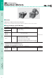
Datasheet


17
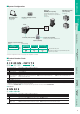
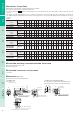
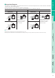
Connection Diagrams
The direction of motor rotation is as viewed from the shaft end of the motor. CW represents the clockwise direction, while CCW
represents the counterclockwise direction.
Connection diagrams are also valid for the equivalent round shaft type.
Specify the type of the capacitor to be included by entering J, U or E in the box (
) within the model name.
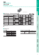
Lead Wire Type Terminal Box Type
2IK6GN-AW2
2IK6GN-CW2
2IK6GN-AW2T
2IK6GN-CW2T
2IK6GN-SW2T
Counterclockwise
Counterclockwise
Counterclockwise
Clockwise
Clockwise Clockwise
Clockwise
Counterclockwise
2IK6GN-SW2
CW
U1
U2
Z2
Capacitor
L
N
Motor
PE
U1
U2
Z2
L
N
Motor
Capacitor
CCW
PE
U1
U2
Z2
Red
White
Black
Motor
PE
CW
L1
(
R
)
L2
(
S
)
L3
(
T
)
U
V
W
L1
(
R
)
L2
(
S
)
L3
(
T
)
Motor
CW
PE
Capacitor
Black
Red
L
N
White
Motor
PE
CW
White
Red
L
N
Black
Motor
PE
Capacitor
CCW
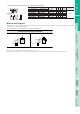
To change the rotation direction,
change any two connections
between R, S and T.
To change the rotation direction,
change any two connections
between U, V and W.
PE: Protective Earth
Note:
Change the direction of single-phase motor rotation only after bringing the motor to a stop.
If an attempt is made to change the direction of rotation while the motor is rotating, motor may ignore reversing command or change its direction of rotation after some delay.
왎
쎲
쎲
쎲
World
K
Series
Induction Motors
Reversible Motors
Electromagnetic Brake
Motors
Torque Motors
Right-Angle
Gearheads
Brake Pack
SB50W
Accessories
2-Pole,
High-Speed Type