
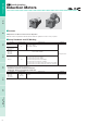
Datasheet

12
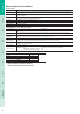
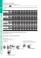
Gearmotor – Torque Table
Gearheads are sold separately. Decimal gearheads are not available.
Enter the gear ratio in the box (
) within the model name.
A colored background indicates gear shaft rotation in the same direction as the motor shaft, while the others rotate in the opposite
direction.
The speed is calculated by dividing the motor's synchronous speed (4-pole type; 50 Hz: 1500 r/min, 60 Hz: 1800 r/min, 2-pole type; 50
Hz: 3000 r/min, 60 Hz: 3600 r/min) by the gear ratio. The actual speed is 2 - 33% less than the displayed value, depending on the size of
the load.
50 Hz Unit = N
m
Model
Speed
r/min
500 416 300 250 200 166 120 100 83 60 50 41 30 25 20 16 15 12.5 10 8.3
Motor/
Gearhead
Gear Ratio
33.65 67.59
12.5
15 18 25 30 36 50 60 75 90 100 120 150 180
0IK1GN-AW2J 0GN
K
0.023 0.028 0.038 0.046 0.058 0.069 0.087 0.1 0.12 0.16 0.19 0.23 0.31 0.38 0.42 0.5 0.56 0.67 0.84 1
0IK1GN-CW2J 0GN
K
0.019 0.023 0.032 0.039 0.049 0.058 0.073 0.088 0.11 0.13 0.16 0.19 0.26 0.32 0.35 0.42 0.47 0.57 0.71 0.85
Unit = N
m
Model
Speed
r/min
1000 833 600 500 400 333 240 200 166 120 100 83 60 50 40 33 30 25 20 16
Motor/
Gearhead
Gear Ratio
33.65 67.59
12.5
15 18 25 30 36 50 60 75 90 100 120 150 180
0IK3GN-BW2J 0GN
K
0.029 0.035 0.049 0.058 0.073 0.087 0.11 0.13 0.16 0.2 0.24 0.29 0.4 0.48 0.53 0.64 0.71 0.85 1 1
0IK3GN-DW2J 0GN
K
0.023 0.028 0.038 0.046 0.058 0.069 0.087 0.1 0.12 0.16 0.19 0.23 0.31 0.38 0.42 0.5 0.56 0.67 0.84 1
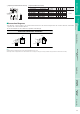
60 Hz Unit = N
m
Model
Speed
r/min
600 500 360 300 240 200 144 120 100 72 60 50 36 30 24 20 18 15 12 10
Motor/
Gearhead
Gear Ratio
33.65 67.59
12.5
15 18 25 30 36 50 60 75 90 100 120 150 180
0IK1GN-AW2J
0IK1GN-AW3U
0IK1GN-CW2J
0GN
K
0.019 0.023 0.032 0.039 0.049 0.058 0.073 0.088 0.11 0.13 0.16 0.19 0.26 0.32 0.35 0.42 0.47 0.57 0.71 0.85
Unit = N
m
Model
Speed
r/min
1200 1000 720 600 480 400 288 240 200 144 120 100 72 60 48 40 36 30 24 20
Motor/
Gearhead
Gear Ratio
33.65 67.59
12.5
15 18 25 30 36 50 60 75 90 100 120 150 180
0IK3GN-BW2J
0IK3GN-BW3U
0GN
K
0.024 0.029 0.041 0.049 0.061 0.073 0.091 0.11 0.13 0.17 0.2 0.24 0.33 0.4 0.44 0.53 0.59 0.71 0.89 1
0IK3GN-DW2J 0GN
K
0.023 0.028 0.038 0.046 0.058 0.069 0.087 0.1 0.12 0.16 0.19 0.23 0.31 0.38 0.42 0.5 0.56 0.67 0.84 1
Permissible Overhung Load and Permissible Thrust Load
Motor (Round shaft type) ➜ Page 107
Gearhead ➜ Page 107
Permissible Load Inertia J for Gearhead
➜ Page 107
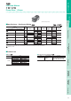
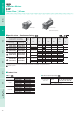
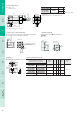
Dimensions (Unit = mm)
Mounting screws are included with gearheads.
왎
쎲
쎲
쎲
쎲
앳
앳
왎
왎
왎
Lead Wire Type
Mass: Motor 0.3 kg
Gearhead 0.2 kg
4
8
⫾
0
.
5
42
10
8
18
26
3
4.5
12
5
Motor Leads 300 mm Length
UL Style 3266, AWG22
16.5
28
7.5
2
0
5
⫺
0.012 (
h7
)
20
60
42
4⫻
3.5 Thru
Protective Earth Terminal
M4
7 max.
앳 Shaft Section of Round Shaft Type
The mass and motor's dimensions (excluding the shaft
section) are the same as those of the pinion shaft type.
20
1.5
4
8
⫾
0.5
4⫻
3.5 Thru
5
⫺
0.012
(
h7
)
0
42
42
10
0
37.6
⫺
0.025
(
h7
)
Protective Earth Terminal
M4
7 max.
앳
10
7.25
Detail Drawing of Protective Earth Terminal
Protective Earth Terminal M4
World
K
Series
1 W / 3 W 6 W 15 W 25 W 40 W 60 W 90 W
2-Pole, High-Speed
40 W
⬃
150 W