GPC Plus Controller General Information & Application Guide
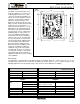
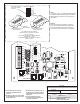
OE331-21-GPC GPC Plus Controller D1 6.2“ CX1 RN1 1 CX3 U3 C21 CX2 U2 U1 CX4 RLY1 U4 V1 D2 TB1 COMM V2 T SHLD RLY2 V3 U5 PAL RS-485 1 EPROM RAM RLY3 COMM (1 MEG) YS101816 REV.
C21 U3 CX1 CX2 U1 CX4 RLY1 U4 V1 D2 TB1 COMM V2 T SHLD RLY2 U5 PAL RS-485 COMM RAM RLY3 RN3 HH (1 MEG) YS101816 REV. 2 U6 D4 LD8 LED1 TUC-5R PLUS RN2 1 COM4-5 RLY4 P1 +VREF TB2 D5 CX6 5.
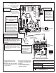
This Switch Should Be In The OFF Position As Shown ADDRESS ADD Note: The Power To The Controller Must Be Removed And Reconnected After Changing The Address Switch Settings In Order For Any Changes To Take Effect. S S ES R D AD ES R D AD 1 2 4 8 16 32 TOKEN NETWORK D AD D AD Caution Disconnect All Communication Loop Wiring From The Controller Before Removing Power From The Controller. Reconnect Power And Then Reconnect Communication Loop Wiring.
General Purpose Controller (GPCPlus ) January 31, 2005 Description The GPCPlus is a controller designed to “fill in the blanks” between standard off the shelf programs and minor non-standard applications. An example of a non-standard application might be exhaust fan control, based on building pressure or a simple boiler enable controller based on schedules or outdoor air temperature.
accesses the configuration for the selected item and a right click accesses the force mode options if any are available.
Week Schedules & Holidays 3
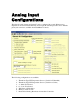
Analog Input Configurations The first five analog inputs and input #7 can be configured in several different ways. Input #6 can be used for Static Pressure and accepts the standard pressure sensor with the phone jack connector, available from WattMaster Controls. The following configurations are available: 1. 2. 3. 4. 5. 6. 7.
8. Read Global Binary Broadcast from another Controller 9. Sensor #6 can be assigned to read Static Pressure Each input is separately configured so combinations of any type of input on the same controller are possible. All readings can be overridden to specific values for test purposes. All thermister sensors can also be calibrated by entering positive or negative offsets to be applied to the current readings.
Any or all readings can also be “broadcast” to other controllers on the communications loop. For example, the Outdoor Air Temperature is broadcast on channel #2 by any unit that happens to have the sensor attached. If none of the standard package units have the outdoor air sensor attached, you could attach it to the GPCPlus and select it for broadcast on channel #2. All other controllers would “hear” the broadcast and use it in their normal operations.
Each input can also have an appendix selected to display with the reading to make them more user friendly. The possible appendix values are: • • • • • • • • • • • • • (None) RH% % °F °C PPM PSI “WG “ Ft.
Wall Sensor Slide Offset If you have configured a specific input to be connected to one of WattMasters’ standard OE212 or OE213 Flush Mount Wall Sensors which contain the optional slide offset, be sure to enter a value for “Maximum Slide Offset Effect”. This tells the controller how much effect to have on the selected setpoints when the slide is fully deflected up or down. When the slide is in the “center” position, it has no effect on the current setpoints.
to 72.0°F. If the slide is pushed down, the Hi Limit Setpoint will drop to 70.0°F and the Lo Limit Setpoint to 68.0°F. Push-Button Override If you have configured a specific input to be connected to one of WattMasters’ standard OE211 or OE213 Flush Mount Wall Sensors which contain the optional push-button override, be sure to enter a value for “Push-Button Override Duration”. To use this option you must select which schedule will be affected by the override event. (See screen below).
Analog Input #6 This analog input is reserved for Duct Static Pressure. This value can then be used to monitor the duct static or to actually control the duct static using an analog output and driving either inlet vanes or a VFD controller. It is not recommended that you attempt to use relays to control the duct static pressure, although this reading can be selected as a control source on the relay configuration screen.
Relay Output Configuration Control Methods Each individual output relay can be configured separately for one of the following methods of control listed below.
8 9 10 11 = = = = Follow Global Binary Only Ventilation Control Lead Relay for Lead/Lag Control Lag Relay for Lead/Lag Control Control/Reset Sources The Control Source is also selectable. This control source can be an analog value or an on/off contact closure. The list of possible sources is shown below.
such as outdoor air temperature. If no reset is required, simply enter the same values for the Control Source Hi and Lo Limit Setpoints. No Reset Source is required. If you do need the main Control Source Setpoint to reset, this is the range over which the Reset Source must change to cause the controlling setpoint to reset from the Lo Limit to the Hi Limit values you entered. For example: you want to reset the enable/disable point for a boiler enable signal based on the changing outdoor air temperature.
Run Time Alarm If the selected relay output is controlling a device that needs periodic maintenance, you can enter a Run Time Alarm Delay period that, once exceeded, generates an alarm condition that will notify the user when it occurs. If you need to protect the equipment you can select the Disable Relay box and the relay will de-activate once this run time has been exceeded.
Ventilation Control You can configure an output to operate in a ventilation control mode. This means that the output is active for the Vent Mode ON Time and then cycles off for the Vent Mode OFF Time. If the output is not enabled by a schedule or another relay, it will continue to cycle indefinitely at this On/Off rate.
Analog Output Configuration Two Proportional Outputs ( 0 - 10 VDC ) are available to the user. This output operates using standard floating point control or a modified Proportional/Derivative control as configured by the user. The controlling setpoint can be reset by any other sensor reading or the outdoor air temperature and the output voltage range can be limited by the user to some range other than the standard 0 - 10 VDC.
7 = Proportional Reset Signal 8 = Economizer Control 9 = Lead/Lag Pump VFD Control Possible Control Sources 0 = Not Configured 1 = Sensor Input #1 2 = Sensor Input #2 3 = Sensor Input #3 4 = Sensor Input #4 5 = Sensor Input #5 6 = Sensor Input #7 7 = Static Pressure 8 = Outdoor Air 9 = Calculated Wetbulb Temperature (Requires a sensor configured for Humidity) Floating Point Control If you select Direct or Reverse Acting Floating Point Control, this means that the output voltage on Direct Acting increases
Economizer Control If you have configured the GPCPlus as a very simple Air Handling Unit, it has the ability to control the outside air dampers in a true first stage economizer cooling mode. This mode requires a Minimum Ventilation position that it maintains whenever the economizer is not enabled for cooling. It also needs to know which relay has been configured as the first compressor stage.
Lead/Lag Pump VFD Control If you are using the GPCPlus as a Lead/Lag controller and you need to maintain loop pressure or some other analog signal, configure an output for this method of control. Then all you need to do is enter the control setpoint on the Lead Relay configuration screen and this output will attempt to modulate and maintain that level of control while the Lead/Lag control is active.
Sample Configurations Sample #1 The user would like to control 4 boilers. Each boiler is controlled from the same Water Temperature sensor but at a different temperature reading. Once a boiler is activated it must remain on at least 5 minutes and if a boiler is de-activated it must remain off at least 10 minutes. Additionally, the boilers are locked out when the Outdoor Air Temperature is above 65°F.
Analog Input #2 Configured as Outdoor Air Thermister Sensor Notice that we set this reading to broadcast on Global Analog Channel #2. That is because the Outside Air is normally read by one controller on a job and the remaining controllers look at Global Analog #2 for this value, including the GPC Plus. Even if this is the only controller on the job, you must set it to broadcast the outside air so the GPC Plus can “see” what the OA Temperature is.
Relay Output #1 Programming ( Used for Outdoor Air Enable / Disable ) NOTE: Nothing is physically connected to Relay #1. Its only use is to enable or disable the other relays.
Relay Output #2 Programming ( Used for Boiler #1 ) As you can see, the first boiler stage is enabled to operate if the water temperature is below 175°F and will remain on until it rises to 190°F. This first stage can only operate if the outdoor air enabling relay #1 is active. Once activated, the boiler must remain on for 5 minutes (300 seconds) and once de-activated it must remain off for 10 minutes (600 seconds).
Relay Output #3 Programming ( Used for Boiler #2 ) The second boiler stage is enabled to operate if the water temperature is below 170°F and will remain on until it rises to 180°F. The second stage can only operate if the first boiler stage relay #2 has been active for at least 5 minutes. Once activated, this stage must remain on for 5 minutes and once de-activated it must remain off for 10 minutes.
Relay Output #4 Programming ( Used for Boiler #3 ) The third boiler stage is enabled to operate if the water temperature is below 160°F and will remain on until it rises to 175°F. The third stage can only operate if the second boiler stage relay #3 has been active for at least 5 minutes. Once activated, this stage must remain on for 5 minutes and once de-activated it must remain off for 10 minutes.
Relay Output #5 Programming ( Used for Boiler #4 ) The fourth boiler stage is enabled to operate if the water temperature is below 150°F and will remain on until it rises to 170°F. The fourth stage can only operate if the third boiler stage relay #4 has been active for at least 5 minutes. Once activated, this stage must remain on for 5 minutes and once de-activated it must remain off for 10 minutes.
Operation Relay #1 enables the boilers to operate if the outdoor air temperature is below the low setpoint and the schedule is occupied. Each boiler is enabled to operate if the previous boiler is currently active and has been on for at least 5 minutes. All four boilers monitor the same analog input sensor for the Water Temperature reading.
This next sample screen shows that the outdoor air temperature has dropped enough to enable the boilers to operate. The system has been running long enough to satisfy all 4 Boilers 5 Minute Starting delay so they are all active at this point. It took roughly 20 minutes to get all 5 relays active since each has a 5 minute Staging Delay time period.
Sample #2 The user would like to use the GPC Plus as a Lead/Lag Air Handling Unit Controller. The installation is located in a critical area that does not tolerate the space temperature going out of control. The method chosen was to install a backup AHU that would take over in case of failure on the Lead AHU. Also, since the units are identical, the owner wanted to equalize the run-times to lengthen the time between routine maintenance service calls.
back alarm condition because the Lead/Lag control should have already generated an alarm if something was wrong and the standby AHU was called into action. Be sure to check the Alarming Enabled box if you want this alarm to be reported back to the PRISM screen or to a Remote Pager. Analog Input #2 - #7 The remaining inputs are not required for this program. Relay Output #1 Programming ( Used for Lead AHU Enable Signal ) This relay was chosen to be the Lead control output and was connected to AHU #1.
Relay Output #2 Programming ( Used for Lag AHU Enable Signal ) There are no other settings required for the Lag Controller. All control logic from the Lead relay is used in the decision making process.
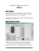
Main Status Screen ( Normal Operations ) As you can see on the Status Screen shown above, the unit is operating normally and the Supply Temperature is at 51.9°F, well within the normal operating range and no alarms are currently active. There are no schedules active since this unit is required to operate 24 hours a day. The relay outputs will operate their control modes around the clock if no schedule was selected on the relay configuration screen.
Main Status Screen ( Failure Mode ) The Supply Air rose to 61.9°F and the Lag AHU was activated. The alarm screen indicates the Lead AHU failure.
Both AHU’s are now off because the Lag AHU failed to lower the Supply Air below 60°F.
The alarm screen indicates both outputs failed to control the Supply Temperature. At this point, the service personnel will need to correct the problem and then select the Reset Pump/Fan button to restart the GPC Plus Lead/Lag control sequence. Although the button and alarm indicators show Lead Pump / Fan indicators, the outputs are not limited to those types of control. You just need to understand that the Lead Pump / Fan controls AHU #1 in this sample and Standby Pump / Fan controls AHU #2.
Form: OR-GPCPlus-APP-01A Printed in the USA March 2005 All rights reserved Copyright 2005 WattMaster Controls Inc. • 8500 NW River Park Drive • Parkville MO • 64152 Phone (816) 505-1100 www.wattmaster.