CONTENTS SAFETY INSTRUCTION 2 CAUTIONS 4 FCC RF INTERFERENCE STATEMENT 5 CONNECTING WITH EXTERNAL EQUIPMENT 6 RESOLUTION 7 CONTROLS AND FUNCTIONS 8 REAR VIEW 12 D-SUB CONNECTOR PIN ASSIGNMENTS 13 POWER MANAGEMENT 14 SPECIFICATIONS 15 TROUBLESHOOTING GUIDE 16 T his Moni tor wa s M anufa ct ure d by ISO 9001 Ce rt ifi ed Fa cto ry 1
SAFETY INSTRUCTION 1. Read all of these instructions. 2. Save these instructions for later use. 3. Follow all warnings and instructions marked on the product. 4. Unplug this product from the wall outlet before cleaning. Do not use liquid cleaners or aerosol cleaners. Use a damp cloth for cleaning. 5. Do not use this product near water. 6. Do not place this product on an unstable cart, stand or table. The product may fall, causing serious damage to the product. 7.
SAFETY INSTRUCTION 14. Unplug this product from the wall outlet and refer servicing to qualified service personnel under the following conditions. A. When the power cord or plug is damaged or frayed. B. If liquid has been spilled into the product. C. If the product has been exposed to rain or water. D. If the Product does not operate normally when the operating instructions are followed.
CAUTIONS NEVER REMOVE THE BACK COVER Removal of the back cover should be carried out only by qualified personnel. DO NOT USE IN HOSTILE ENVIRONMENTS To prevent shock or fire hazard, do not expose the unit to rain or moisture. This unit is designed to be used in the office or home. Do not subject the unit to vibrations, dust of corrosive gases. KEEP IN A WELL VENTILATED PLACE Ventilation holes are provided on the cabinet to prevent the temperature from rising.
FCC RF INTERFERENCE STATEMENT NOTE : This equipment has been tested and found to comply with the limits for a Class B digital device, pursuant to Part 15 of the FCC Rules. These limits are designed to provide reasonable protection against harmful interference in a residential installation. This equipment generates, uses and can radiate radio frequency energy and, if not installed and used in accordance with the instructions, may cause harmful interference to radio communications.
CONNECTING WITH EXTERNAL EQUIPMENT C A UT I O N Be sure to turn off the power of your computer before connecting the monitor. 1. CONNECT THE VIDEO SIGNAL CABLE A. Connect one end of the signal cable to the back panel of the monitor and connect the other end to the graphic card on back of the computer. B. Secure the connection with the screws on the plug. 2. CONNECT THE POWER CORD A. Connect the plug of the AC/DC adaptor to the monitor. B.
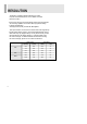
RESOLUTION This monitor is a digitally-controlled multi-frequency monitor. It operates at horizontal frequencies of 31 to 50KHz and vertical frequencies of 60Hz. Because of its micro processor-based designs it offers auto-synchronization and auto-sizing capabilities. This monitor offers 6 programmed settings as listed in the table below. And designs its best quality at 1024X768, 48KHz@60Hz. These 6 preset modes cover most of the common video modes supported by popular graphic adaptors.
CONTROLS AND FUNCTIONS D. ADJUST BUTTONS (DOWN & UP) C. SELECT BUTTON B. MENU BUTTON A. POWER ON/OFF( POWER INDICATOR(LED) A. POWER SWITCH ) Turns the power ON or OFF. There will be a few seconds delay before the display appears. The power LED(next to the power switch) lights when the power is turned ON. The power is turned off by pressing the power switch again and the power LED goes out. B. MENU Activates and exits the On Screen Display. MENU: Auto Adjustment, Horz.
CONTROLS AND FUNCTIONS MENU activates when you press the Menu button. C. SELECT The select button allows user to activate the desired adjustment with changing the adjustment bar to blue. D. ADJUST The Adjust button allows user to choose the icons (controls) in the menu. Pressing the adjust button will step through all available adjustment icons (controls).
CONTROLS AND FUNCTIONS 1. SELF-TEST DISPLAY When there is no connection, the On Screen Display will show for 5 seconds. DPMS Power Saving Mode 2. OSD MENU DESCRIPTION Auto Adjustment Auto Geometry & Auto Color Balance Horz. Position Moves images horizontally on screen left(up) or right(down„ ). Vertical Position Moves images vertically on screen up or down. Horizontal Size Adjusts the horizontal size of the screen’s image. Phase Adjusts the focus of the screen’s image.
CONTROLS AND FUNCTIONS OSD Language Selects a language among English, German, French, Spanish, Italian. Advanced Factory Preset, Sharpness, DOS/GFX, OSD Horizontal Position, OSD Vertical Position Factory Preset Press “select” key to reset all setting to the factory default value. Sharpness Adjusts the sharpness of the screen’s image. DOS/GFX Selects text or graphic mode. OSD Horizontal Position Displays the OSD position menu. Moves the OSD position to left/right.
REAR VIEW F. DC JACK AC/DC adaptor connection. G. D-SUB CONNECTOR Connect to the video signal cable. F. DC JACK G. D-SUB CONNECTOR AC/DC ADAPTOR 1 2 1 GROUND 2 DC+12V out ACCESSORY 1. POWER CORD 2. INSTRUCTION MANUAL 3. AC/DC ADAPTOR 4.
D-SUB CONNECTOR PIN ASSIGNMENTS PIN ASSIGNMENTS Pin 1 RED VIDEO 9 2 GREEN VIDEO 10 3 BLUE VIDEO 11 4 12 SDA(for DDC) 5 GROUND 13 H-SYNC.(or H+V SYNC.) 6 RED GROUND 14 V-SYNC.
POWER MANAGEMENT This monitor features a power management system to “power down” upon receipt of the VESA DPMS(The display power management signaling) from a VESA DPMS video card. The VESA DPMS-compliant video card performs this signaling system through not sending horizontal, vertical, or sync signal. This monitor enters an appropriate mode through identifying each of the three modes of the signaling system.
SPECIFICATIONS LCD Type 15.0" Diagonal AM-TFT(Active-Matrix) DOT PITCH: 0.297mm BRIGHTNESS: 250cd/ m2 (Typical) CONTRAST RATIO: 300:1(Typical) RESPONSE TIME: 20 msec(Typical) RESOLUTION(H x V) 1024X768 @60Hz FREQUENCY HORIZONTAL: 31-50KHz VERTICAL: 60Hz INPUT SIGNAL VIDEO(Analog 0.7Vp-p / 75ohm) SYNC(Separate and Composite TTL Level) ACTIVE DISPLAY AREA (W x H) 304mm X 228mm DIMENSIONS (W x D x H) 392mm X 196mm X 362mm WEIGHT Net Weight : 5.3Kg Gross Weight : 7.
TROUBLESHOOTING GUIDE TROUBLE TROUBLESHOOTING TIP No image on display screen 1. Check that power cord of the Monitor have been connected securely into wall outlet or grounded extension cable or strip. 2. Power switch should be in the ON position and LED is lit. 3. Check that the Brightness and/or the Contrast adjustments of the Display have not been turned down to minimum levels. “No signal, Check signal Cable” message on screen 1.