
Telescopes & Binoculars Air Conditioner User Manual


3
ADDITIONAL MATERIAL REQUIRED FOR INSTALLATION (NOT SUPPLIED)
●
Deoxidized annealed copper tube for refrigerant tubing connecting the units of the system; it has to be insulated with foamed polyethylene
(min. thickness 8mm).
●
PVC pipe for condensate drain pipe (ø int.18mm) in lenght suitable to let the condensate flow into the outside drainage.
●
Anti-freeze oil for flare connections (about 30g.).
●
Electric wire: use insulated copper wires of size and length as shown in the table “ELECTRICAL DATA” and at paragraph “SYSTEM WIRING
DIAGRAMS”.
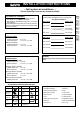
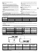
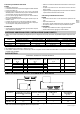
ELECTRICAL DATA
LENGTH, WIRE SIZE AND DELAYED FUSE
TUBING LENGTH AND ELEVATION DIFFERENCE LIMITS
(go on page 4)
EG
OUTER DIAMETER MIN. THICKNESS OUTER DIAMETER MIN. THICKNESS
UR9X - UR12X 6,35 mm 0,8 mm 9,52 mm 0,8 mm
UR18X 6,35 mm 0,8 mm 12,7 mm 0,8 mm
UR22X 6,35 mm 0,8 mm 15,88 mm 1 mm
LARGE TUBE
MODEL
NARROW TUBE
Power supply wiring length Power line length Control line length
(A) m (B) m (C) m
80 2 80 2
140 3,5 140 3,5
50 2 50 2
90 3,5 90 3,5
CR/CLR18X 22 2,5 30 2,5 30 2,5 20 A
CR22X 16 2,5 30 2,5 30 2,5 20 A
0,75
10 A
Delayed fuse
0,75
10 A
MODEL
mm
2
mm
2
mm
2
CR9X
CR12X
160
160
UR9X 7,5 15 7 15
UR12X 7,5 20 7 25
UR18X - 22X 7,5 30 7 25
MODEL
MAX. ALLOWABLE LIMIT OF TUBING LIMIT OF ELEVATION REQUIRED AMOUNT OF
TUBING LENGTH AT LENGTH DIFFERENCE ADDITIOONAL
SHIPMENT H REFRIGERANT
(m) (m) (m) (g / m)*
* For every meter of tube more than standard lenght at shipment, add refrigerant as shown in the table. No additional charge
of compressor oil is necessary.
Installation site selection - Indoor unit
AVOID
• Direct sunlight.
• Nearby heat sources that may affect unit performance.
• Areas where leakage of flammable gas may be expected.
• Locations where large amounts of oil mist may occur (such as
in kitchen or near factory equipment) because oil contamination
can cause operation problems and may deform plastic surfaces
and parts of the unit.
• Unsteady locations that will cause noise or possible water
leakage.
• Locations where the remote control unit will be splashed with
water or affected by dampness or humidity.
• To make holes in areas where electrical wiring or conduits are
located.
DO
• Select an appropriate position from which every corner of the
room can be uniformily cooled.
• Select a sufficiently strong location to support the weight of the
unit.
• Select a location where tubing and drain hose have the shortest
run to the outside.
• Allow access for operation and maintenance as well as
unrestricted air flow around the unit.
Installation site selection - Outdoor unit
AVOID
• Heat sources, exhaust fans.
• Direct sunlight.
• Damp, humid or uneven locations.
• To make holes in areas where electrical wiring or conduits are
located.
DO
• Choose places as cool as possible and well ventilated.
• use lug bolts or equal to bolt down the unit, reducing vibration
and noise.