
Telescopes & Binoculars Telescope User Manual


4
1 Azimuth encoder board
1 Encoder connector board
5 Encoder board mounting wood screws
1 Brass bushing
1 Encoder disk
1 Azimuth axis hex-head screw (length 2.25")
2 Fender washers (diameter 1")
1 Hex lock nut
4 Altitude bearing cylinders
4 Altitude bearing cylinder screws (length 1-3/4",
black)
1 Vertical stop knob
1 Nylon spacer (white)
3 Flat washers (2x
1
/
16
" thick, 1x
1
/
32
" thick)
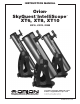
(Please note: Unless otherwise specified, all images and pic-
tures in this manual are of the SkyQuest XT8.)
2. Assembly
Now that you have unpacked the boxes and familiarized your-
self with all the parts in front of you, it’s time to begin
assembly. The optics of the telescope are already installed in
the tube, so most of the required assembly concerns the
Dobsonian base.
Assembly of the Dobsonian Base
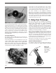
Refer to Figure 2 during base assembly. The base need only
be assembled once, unless you disassemble it for long-term
storage. The assembly process takes about 30 minutes and
requires, in addition to the supplied tools, a Phillips screwdriv-
er, and two adjustable crescent wrenches.You can substitute
a 7/16" crescent wrench for one of the adjustable crescent
wrenches, or use a pair of pliers.
The azimuth encoder board and other encoder items should
be installed, even if you do not plan to use the optional
Computerized Object Locator.The smooth motion of the tele-
scope depends on the installation of these parts.
When tightening screws, tighten them until firm, but be care-
ful not to strip the holes by over-tightening. If you use an
electric screwdriver, do final tightening with a standard screw-
driver to avoid stripping.
1. With a Phillips screwdriver, screw the plastic feet into the
underside of the ground baseplate (A) using the self-tap-
ping wood screws provided. Insert the screws through the
feet and thread them into the predrilled starter holes.
2. Loosely attach the front brace (B) to the two side panels
(C) with six of the base assembly screws in the predrilled
holes. Use the 4mm hex wrench to tighten the screws.The
side panels should be oriented so the SkyQuest
IntelliScope labels are facing outward. Do not completely
tighten the screws yet.
3. Connect the two side panels (C) with the front brace
attached to the top baseplate (D) with the remaining six
base assembly screws in the predrilled holes. The side of
the baseplate with the pilot hole near the square-shaped
cutout should be facing downwards. Tighten all six screws
firmly.
4. Tighten the six side screws installed earlier.
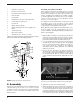
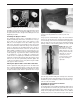
5. Attach the azimuth encoder board (E) to the underside of
the top baseplate (D) (Figure 3). Insert the modular jack
on the encoder board into the square-shaped hole in the
baseplate and align the encoder board so that the small
slotted hole in the board lines up with the predrilled starter
hole, and the large hole lines up with the central hole in
Figure 2. Exploded view of the Dobsonian base.
C
M
B
L
K
D
F
E
A
G
J
H
I
G
G
Figure 3. Installing the azimuth encoder board. Line up the large
hole in the encoder board with the central hole in the top baseplate.
Encoder board
mounting screw
Azimuth encoder board