
Telescopes & Binoculars Binoculars User Manual

33
lar will move when pushed, but will not move on its own. Keep
in mind that as the angle of the binocular approaches the zenith,
the knob tension will need to be increased so that the binocular
does not flop over. Increase the knob tension when bringing the
binocular 40˚ or more from horizontal.
Adjusting Azimuth
Moving the binocular in azimuth (left/right) is a simple matter of turn-
ing the mount on its pivot disk. There is no azimuth lock feature.
Adjusting the Height of the Binocular
A nice feature of the Paragon-Plus binocular mount is that when
the binocular is pointed at an object, the height can be adjusted
for different viewers without moving the binocular off its target. To
do this, simply move the binocular so that only the parallelogram
part of the mount is moving. Do not adjust the tilt angle of the
binocular or move the mount on its pivot disk. Figure 5 shows this
feature in action. Using this feature, people of varying heights will
be able to enjoy binocular views without any crouching over or
straining to reach the binocular.
Adjusting the Paragon-Plus Tripod Height
(#5379)
You may find that the binocular position is too low when the tripod
legs are fully retracted. To raise the height you should extend the
legs of the tripod. You should remove the binocular mount before
extending the tripod legs to prevent the mount and tripod from
falling over.
Each leg of the tripod has two telescoping sections. To extend a
leg, loosen the lever lock knob, then extend the leg. When it has
been extended to the desired length, tighten the lever knob back
down. There is a handy scale printed on the middle segment of
each leg, which can be used to judge the relative height of the
legs.
Although the Paragon-Plus tripod also has an elevator shaft, this
should be used with the binocular mount only after raising the
tripod by use of the legs. Extending the elevator shaft reduces
the stability of the binocular mount. To operate the elevator shaft,
loosen the elevator lock knob and turn the elevator hand crank to
adjust to the desired height. Then tighten the elevator lock knob.
Dual Rubber/Spike Feet (#5379)
The tripod is equipped with dual-purpose feet that consist of a
retractable rubber foot and a metal spike. The rubber feet are
intended for use of the tripod indoors or on a smooth, paved
surface. The metal spikes are desirable for achieving a firm grip
on soft surfaces. To use the rubber feet, thread the foot counter-
clockwise until it stops. In this position, the metal spike will be well
recessed within the rubber. Be sure all three rubber feet are flat
on the floor, not tipped sideways.
To expose the spike feet, thread the rubber foot clockwise until
the spike protrudes from the rubber. In some instances you may
wish to remove the rubber feet altogether so more of the metal
spike is exposed. This can be done by pulling the rubber feet off
their anchors. They can be pressed on again at any time.
Parallelogram Safety Stop
The parallelogram has a safety stop to prevent the aluminum
bars from completely collapsing. This ensures that no fingers will
be caught and crushed by an accidental fast closing of the paral-
lelogram. This feature will also prevent the counterweight from
hitting the tripod.
Astronomical Use
The Paragon-Plus binocular mount allows viewing of subjects
from the horizon all the way up to the zenith. To view objects at
the zenith, adjust the binocular mount and tripod so that they will
be tall enough for you to stand underneath the binocular. Then
adjust the tilt angle of the binocular to point it at the zenith. Stand
underneath the binocular and look up into them. When done
properly, this should resemble Figure 6.
Figure 6. The binocular mount
can be used to view objects at or
near the zenith. Adjust the tripod
so that you can stand under the
binocular to view objects located
high in the sky.
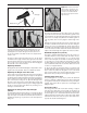
Figure 5. The binocular will remain on target as you adjust
the height using the parallelogram. The standing person in (a) is
looking at the same thing while seated in (b). Note that only the
parallelogram has moved; the tilt angle of the binocular has not.
The pivot disk and binocular altitude should not be adjusted for this
feature to work.
a. b.
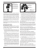
Figure 4. The “tilt angle” of the binoculars
Altitude knob
tilt angle