INSTALLATION INSTRUCTIONS – Split system air conditioner – This air conditioner uses the new refrigerant R410A. DECLARATION OF CONFORMITY This product is marked as it satisfies Directives: – Low voltage no. 73/23 EEC and 93/68 EEC. – Electromagnetic compatibility no. 89/336 ECC, 92/31 EEC and 93/68 EEC. This declaration will become void in case of misuse and/or non observance though partial of manufacturer's installation and/or operating instructions.
• Ground the unit following local electrical codes. • The Yellow/Green wire cannot be used for any connection different from the ground connection. • Connect all wiring tightly. Loose wiring may cause overheating at connection points and a possible fire hazard. • Do not allow wiring to touch the refrigerant tubing, compressor, or any moving parts of the fan. • Do not use multi-core cable when wiring the power supply and control lines. Use separate cables for each type of line.
• Select a sufficiently strong location to support the weight of the unit. • Select a location where tubing and drain hose have the shortest run to the outside. • Allow access for operation and maintenance as well as unrestricted air flow around the unit. Installation site selection - Indoor unit AVOID • Direct sunlight. • Nearby heat sources that may affect unit performance. • Areas where leakage of flammable gas may be expected.
ISTRUZIONI DI INSTALLAZIONE – Condizionatore d’aria Split System – Questo condizionatore contiene il nuovo refrigerante R410A. DICHIARAZIONE DI CONFORMITÀ Questo prodotto è marcato in quanto conforme alle Direttive: – Bassa Tensione n. 73/23 CEE e 93/68 CEE. – Compatibilità Elettromagnetica n. 89/336 CEE, 92/31 CEE e 93/68 CEE.
IMPORTANTE! Leggere prima di iniziare l’installazione • Eseguire la messa a terra dell’unità secondo le norme elettriche locali. • Il conduttore giallo/verde non può essere utilizzato per collegamenti diversi dalla messa a terra. • Fissare bene i cavi. Collegamenti inadeguati possono causare surriscaldamento e un possibile incendio. • I cavi elettrici non devono venire a contatto con i tubi refrigeranti, il compressore o le parti mobili del ventilatore.
Scelta del luogo di installazione unità interna EVITARE • L’esposizione diretta al sole. • La vicinanza a fonti di calore che possono danneggiare la struttura dell’unità. • Presenza di perdite di gas. • Presenza di vapori d’olio (come in una cucina o vicino a macchinari industriali) perché la contaminazione d’olio può provocare malfunzionamento e può deformare superfici e particolari in plastica dell’unità.
NOTICE D’INSTALLATION – Climatiseur split – Ce climatiseur utilise le nouveau réfrigérant R410A. DECLARATION DE CONFORMITE Ce produit est marqué puisque il est conforme aux Directives: – Basse Tension n. 73/23 CEE et 93/68 CEE. – Compatibilité Electromagnétique n. 89/336 CEE, 92/31 CEE et 93/68 CEE. Cette déclaration sera nulle en cas d'une utilisation différente de celle déclarée par le Constructeur et/ou de la nonobservation, même partielle des instructions d'installation et/ou d’utilisation.
• Effectuez la mise à la terre de l'appareil en respectant les réglementations électriques locales. • Le câble jaune/vert ne peut en aucun cas être utilisé pour toute autre connexion que celle de la mise à la terre. • Serrez fermement toutes les connexions. Un câble mal fixé peut entraîner une surchauffe au point de connexion et présenter un danger potentiel d'incendie. • Il ne faut en aucun cas laisser les câbles toucher la tuyauterie du réfrigérant, le compresseur ou toute pièce mobile.
Choix de l'emplacement d'installation - Appareil intérieur EVITEZ • L'exposition directe au soleil. • La proximité de sources de chaleur qui pourraient affecter la structure de l'appareil. • Les zones dans lesquelles il existe une possibilité de fuites de gaz.
INSTALLATIONSANLEITUNGEN – Zweirohrsystem-Klimaanlage – Diese Klimagerät enthält den neue Kühlmittel R410A. KONFORMITÄTSERKLÄRUNG Dieses Produkt ist mit -Zeichen gekennzeichnet, weil es den folgenden Richtlinien entspricht: – Niederspannungsrichtilinie 73/23 EWG und 93/68 EWG. – Elektromagnetische Verträglichkeit 89/336 EWG, 92/31 EWG und 93/68 EWG.
WICHTIG! Bitte vor Arbeitsbeginn lesen • • Diese Klimaanlage entspricht strengen Sicherheits- und Betriebsnormen. Für den Installateur oder Bediener dieser Anlage ist es wichtig, sie so einzubauen oder zu warten, daß ein sicherer und effizienter Betrieb gewährleistet wird. • • Für eine sichere Installation und einen sorgenfreien Betrieb müssen Sie: • Diese Anleitungsbroschüre vor Arbeitsbeginn aufmerksam lesen. • Jeden Installations- und Reparaturschritt entsprechend der Beschreibung ausführen.
Wahl des Installationsortes - Innenraumgerät VERMEIDEN SIE • Direkte Sonneneinstrahlung. • Wärmequellen in der Nähe des Gerätes, die dessen Leistungsfähigkeit beeinflussen könnten. • Bereiche, wo Leckgasen erwartet werden können. • Die Installationen an Stellen, an denen die Geräte starkem Öldunst ausgesetzt sind (wie z.B. in Küchen oder in der Nähe von Fabrikmaschinen). Ölverschmutung kann zu Betriebstörungen und zur Verformung von Plastikoberflächen und -teilen des Gerätes führen.
INSTRUCCIONES DE INSTALACION – Acondicionador de aire Spli System – Este acondicionador utiliza el nuevo refrigerante R410A. DECLARACION DE CONFORMIDAD Este Producto está marcado porque responde a las Directivas: – Baja Tensión n° 73/23 CEE y 93/68 CEE. – Compatibilidad Electromagnetica n° 89/336 CEE, 92/31 CEE y 93/68 CEE.
• Realizar la puesta a tierra de la unidad siguiendo las normas eléctricas locales. • El conductor amarillo/verde no se puede utilizar para conexiones que no sean la de tierra. • Fijar bien los cables. Un error en las uniones puede provocar recalentamiento o un posible incendio. • No deje que ninguna conexión contacte con el tubo de refrigerante, compresor o parte móviles del ventilador. • No use cable coaxial para cablear las líneas de potencia y las de control.
Dónde instalar la unidad interior EVITAR • La exposición directa al sol. • Zonas expuestas a fuentes de calor que puedan dañar la estructura de la unidad. • Pérdidas de gas. • Vapores de aceite (como en una cocina o cerca de máquinas industriales), ya que el contacto con el aceite puede provocar mal funcionamiento y puede deformar las superficies de plástico de la unidad. • Lugares donde el punto de apoyo no sea completamente estable, ya que pueden provocar vibraciones, ruidos y posibles pérdidas de agua.
INSTRUCCIONES DE INSTALACION – Acondicionador de aire Spli System – Este acondicionador utiliza o novo refrigerante R410A. DECLARAÇÃO DE CONFORMIDADE Este produto tem a marca porque responde às Directrizes: – Baixa tensão N° 73/23/CEE, 93/68/CEE. – Compatibilidade eletromagnética n° 89/336/CEE, 92/31/CEE e 93/68/CEE. Esta declaração será considerada nula se a sua utilização for diferente da do fabricante e/ou se não forem seguidas, mesmo que parcialmente, as instruções de instalação e/ou de modo de emprego.
IMPORTANTE ! Queira ler antes de colocar a unidade em funcionamento • Ligue a unidade à terra seguindo as normas locais de eletricidade. • O fio AMARELO/VERDE só deve ser usado para ligação à terra. • Faça todas a ligações elétricas bem apertadas. Fios elétricos frouxos podem causar superaquecimento nos pontos de ligação e um possível perigo de incêndio. • Não deixe que a instalação elétrica toque na tubagem de refrigeração, no compressor ou em quaisquer peças móveis da ventoinha.
Escolha do Local de Instalação da Unidade para Interior EVITE • A luz direta do sol. • Fontes de calor próximas que possam afectar o desempenho da unidade. • Áreas onde se pode esperar que haja fuga de gás inflamável. • A proximidade a vapores oleosos (como em locais tal que cozinhas ou perto de máquinas industriais) pois a contaminação do óleo pode causar um malfuncionamento e pode deformar superfíces ou componentes de unidade em plástico.
ODHGIES TOPOQETHSHS – Diairouvmene" monavde" klimatismouv – MONADES HDH PLHRWMENES ME FUKTIKO R410A. Sunduasmov" montevlwn DHLWSH SUMMORFWSHS To proovn autov fevrei to shvma giativ antapokrivnetai sti" Odhgive"Ú – Camhlhv tavsh ariq. 73/23 EOK kai 93/68 EOK – Hlektromagnhtikhv sumbatikovthta ariq. 89/336 EOK 92/31 EOK kai 93/68 EOK .
SHMANTIKO ! Diabavste prin arcivsete thn egkatavstash • Geiwvste to suvsthma suvmfwna me tou" iscuvonte" topikouv" hlektrikouv" ksnonismouvs. • To kivtrino É pravsino kalwvdio den mporeiv na crhsimopoihqeiv gia avlle" sundevsei" parav movno gia geivwsh. • Staqeropoihvste kalav ta kalwvdia. Aneparkeiv" sundevsei" mporeiv na prokalevsoun uperqevrmansh kai purkagiav. • Ta hlektrikav kalwvdia den prevpei na evrqoun se epafhv me tou" swlhvne" yuvxh", to susmpiesthv hv ta kinhtav tmhvmata tou anemisthvra.
Epiloghv tou cwvrou egkatavstash" th" eswterikhv" monavda" APOFEUGETE • Thn avmesh evkqesh ston hvlio • Oi phgev" qermovthto" mporeiv na kavnoun zhmiav sthn kataskeuhv th" monavda" • Thn topoqevthsh se cwvro me diarroev” aerivou • Thn topoqevthsh se cwvrou" me atmouv" ladiouv ovpw" sthn kouzivna hv kontav se biomhcanikav mhcanhvmata) giativ to lavdi mporeiv na prokalevsei dusleitourgiv a kai na paramorfwv s ei epifav n eie" kai plastikav mikroexarthvmata th" monavda".
INDOOR UNIT • UNITÁ INTERNA • UNITE INTERIEURE • INNENEINHEIT • UNIDAD INTERIOR • UNIDADE INTERIORE • ESWTERIKH MONADA 300 A UR9X - 12X UR18X - 22X D Raumbedarf des Gerätes. A 1500 1700 EG Minimum operation and maintenance area. E Área mínima de funcionamiento y manutención. I Area minima di esercizio e manutenzione. P Área mínima para o funcionamento e manutenção. F Surface minimum de fonctionnement et d’entretien.
E EG I F D E P GR F EG I F D E P GR G EG Drill a 80 mm diameter hole, for the passage of refrigeration pipework, condensate pipework and electrical cable. Insert a PVC pipe in the wall. Eseguire un foro da 80 mm per il passaggio dei tubi del refrigerante, scarico condensa e cavo elettrico. Inserire ed adattare un tubo in plastica nel muro. Faire un trou de diamètre 80 mm. pour le passage des tubes du réfrigérant, de sortie du condensat et câble électrique.
I P A unidade possui um tubo de PVC da bomba de descarga de condensação. A bomba tem uma prevalência de 250 mm além da unidade. Descarregar a condensação por queda com uma pendência mínima de 1:100. A altura máxima necessária no tubo de descarga de condensação deve ser atingida no primeiro trecho próximo à unidade para evitar grandes refluxos de água ao ser desligado o sistema. GR H monavda einva efodiasmevnh apov swlhvma PVC apov thn antliva apostravggish". H antliva brivsketai se uvyo" 250 clst.
D Das elektrische Kabel für die Klemmbrett-Verbindung vorbereiten und sie verbinden. (Sieh elektrische Angaben). Das Kabel an der Drahtklemme befestigen. WARNUNG Stellen Sie sicher, daß alle Kabelverbindungen fest sind. Lose Kabel können zur Überhitzung des Anschlusses oder Fehlfunktion des Gerätes führen. Feuersgefahr mag ebenfalls bestehen.
L M N EG Rear and front flange for the air intake. The value included in the brackets is referred to the model UR18-22X. I Flangia anteriore e posteriore per la ripresa dell’aria. Il valore incluso tra parentesi è riferito al modello UR18-22X. F Bride postérieure pour l’entrée d’air. La valeur dans les parenthèses regarde le modèle UR18-22X. D Rückflansch für Luftansaugung. Die Werte in Klammern beziehen sich auf das Modell UR18-22X. E Brida posterior para la toma de aire.
DUCT FOR FRESH AIR • CONDOTTO PER ARIA ESTERNA DI RINNOVO • CONDUIT POUR LE RENOUVELLEMENT DE L’AIR • LEITUNG FÜR NEUE LUFT • CONDUCTO DE RICAMBIO DEL AIRE • CONDUTA DE RENOVAÇÃO DO AR • AGWGOS AERA ANANEWSHS EG There is a duct connection port for drawing in fresh air. The supplementary fan motor for outside air intake has to be supplied separately and controlled by a bipolar ON-OFF switch with safety fuses. Fresh air flow must be about 10% of the total air flow to avoid operating problems and noise.
OUTDOOR UNIT • UNITÁ ESTERNA • UNITE EXTERIEUR • AUßENEINHEIT • UNIDAD EXTERIOR • UNIDADE EXTERIOR • EXWTERIKH MONADA EG A Minimum operation and maintenance area I Area minima di esercizio e manutenzione. F Surface minimum de fonctionnement et d’entretien. D Raumbedarf des Gerätes. E Area mínima de funcionamiento y manutención. P Área mínima de funcionamento e manutenção.
D EG Remove the side access panel, then connect the power line and interconnecting wires to outdoor unit on the terminal strip and secure them with clamps. I Rimuovere lo sportellino laterale, quindi collegare i fili elettrici di potenza e di collegamento all'unità esterna e bloccarli con i fissacavi. F Enlever la petite porte latérale et ensuite brancher les fils électriques de puissance et de liaison à l'unité exterieure et les fixer par un serre cable. D Die Seitenabdeckung entfernen.
Lubricate H EG I -3 mm 45° F D E P GR I EG Tighten connections using a spanner and a torque wrench; apply specified torque (see table). I Stringere le connessioni utilizzando una chiave fissa e una chiave dinamometrica; attenersi alla tabella dei valori del momento torcente. Serrer les connexions à l'aide d'une clé fixe et d'une clé dynamométrique; respecter les couples de serrage. F J TUBE DIA. TIGHTENING TORQUE 6,35 mm (1/4") Approx. 150 – 200 kgcm (15 - 20 Nm) 9,52 mm (3/8") Approx.
EG K I F D E VACUUM PUMP CAPACITY 100 /h P Tubing length: less than 10 m Tubing length longer than 10 m 10 min. or more 15 min. or more GR NOTE: Use only required tools for R410A EG L I F High pressure D E P Low pressure GR EG M 90° (1/4 turn) Narrow tube I Hex wrench F Wide tube D Valve cap Vacuum hose to manifold valve E P GR Air purging of internal unit and refrigerant tubes. Connect the vacuum pump to the outside unit as shown in the figure.
N 90° (1/4 turn) Narrow tube Hex wrench EG Turn the service valves stem in counterclockwise to fully open the valves. At this point vacuum pump flexible hose can be disconnected. Replace bonnet and flare nut, tighten them to 200 kg/cm with a torghe wrench. I Aprire completamente le valvole di servizio (senso antiorario). A questo punto scollegare il flessibile della pompa del vuoto. Rimontare i cappucci ed il bocchettone, stringere con momento torcente di 200 kg/cm.
O EG The service port on the wide tube service valve uses a Schrader core valve to access the refrigerant system. Therefore, be sure to use a hose connector which has a push-pin inside. I La valvola di servizio del rubinetto dell'unità esterna da utilizzare per il vuoto del sistema, ripristino carica refrigerante e misurazione della pressione di esercizio è del tipo "Schrader". Utilizzare un attacco pompa del vuoto di tipo a spillo.
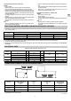
SYSTEM WIRING DIAGRAM • COLLEGAMENTI ELETTRICI DEL SISTEMA • BRANCHEMENTS ELECTRIQUES DU SYSTEME • ELEKTRISCHE ANSCHLÜSSE DES SYSTEMS • CONEXIONES ELECTRICAS DEL SISTEMA • SISTEMA DE INSTALAÇÃO ELÉTRICA • HLEKTRIKH SUNDESH TOU SUSTHMATOS EG COOLING ONLY MODELS I MODELLI SOLO FREDDO CR9X - 12X POWER SUPPLY 220-240V ~ 50Hz F MODELES FROID SEUL D NUR KÜHLUNG MODELLE E MODELOS SOLO REFRIGERACION P MODELOS SOMENTE PARA ARREFECIMENTO GR A EKDOSH MONO YUXHS C B CR-CLR18/22X EG CR9X - 12X HEAT
EG Supply power wire A: Multipolar electric wire. Size and length of the suggested electric wire are showed on table “electrical data”. The wire must be Mod. H05VV-F (according to CEI 20-19 CENELEC HD 22). Make sure the length of the conductors between the fixing point and the terminals allows the straining of the conductors L, N before that of the grounding.
E Cable de alimentación A: Cable eléctrico multipolar; la sección y la longitud del cable eléctrico aconsejado están indicadas dentro de la tabla “Datos eléctricos”. El cable debe ser del tipo H05VV-F (según CEI 20-19 CENELEC HD22). Asegurarse de que la longitud de los conductores entre el punto de fijación del cable y el tablero de bornes es tal que los conductores activos se tiendan antes del conductor de puesta a tierra.
TEST RUN • COME ESEGUIRE LA PROVA DEL CONDIZIONATORE (TEST RUN) • CONTROLE FINALE • ENDKONTROLLE • COMO REALIZAR LA PRUEBA DEL ACONDICIONADOR (TESTRUN) • COMO FAZER O TESTE DO APARELHO DE AR CONDICIONADO • PWS NA KANETE TH DOKIMH TOU KLIMATISTIKOU (TEST RUN) EG I F D E P GR Cooling mode Switch on the power supply. Press the ON/OFF button and change to cooling mode on the remote control unit then press the ON/OFF button again.
REMOTE CONTROL UNIT INSTALLATION • POSIZIONE DI INSTALLAZIONE TELECOMANDO • EMPLACEMENT DE LA COMMANDE A DISTANCE • POSITION DER FERNBEDIENUNG • POSICION DE INSTALACION DEL MANDO A DISTANCIA • POSIÇÃO DA INSTALAÇÃO DA UNIDADE DE CONTROLE REMOTO • QESH TOPOQETHSHS THLECEIRISTHRIOU EG REMOTE CONTROL UNIT INSTALLATION The remote control unit may operated either from a non-fixed position or from a wall-mounted position. To ensure that the air conditioner operates correctly.
A B (1) (2) EG I F D E P GR WALL-MOUNTED NON-FIXED POSITION (A) • Momentarily place the remote control unit in the desired mounting position. • Verify that the remote control unit can operate from this position. • Fix the support at the wall with two screws and hang the remote control unit. WALL-MOUNTED FIXED POSITION (B) • Momentarily place the remote control unit in the desired mounting position. • Verify that the remote control unit can operate from this position.
INFRARED RECEIVER INSTALLATION • INSTALLAZIONE RICEVITORE • INSTALLATION DU RÉCEPTEUR • EMPFÄNGER INSTALLATION • INSTALACIÓN DEL RECEPTOR • INSTALAÇÃO RECEPTOR • EΓKATAΣTAΣH ∆EKTH YΠEPYΘP A EG I F D E P GR Slot a screwdriver by the 2 slits on the cover sides, and separate the cover from the base. Do not lay the receiver cable near any power lines, and do not put it into any raceways or metal tubes together with other power lines. Install the receiver far from electromagnetic interferences.
C EG Perform the earth connection with the terminal on the base, as provided. Complete earth connection and fasten the other end of the cable to the earth terminal in the electric panel. I Do not power the system up, and do not start the unit before having completed the refrigerant piping and the electric installation. Effettuare, se previsto, il collegamento di terra utilizzando il morsetto presente sulla base.
PUMP DOWN EG Pump down means collecting all refrigerant gas in the system back into the outdoor unit without losing gas. Pump down is used when the unit is to be moved of before servicing the refrigerant circuit. E I Pump down significa recuperare tutto il gas refrigerante nell’Unità Esterna senza perdere la carica del sistema. Serve quando si deve riposizionare il condizionatore e per interventi di riparazione sul circuito frigorifero.
TEST OF THE SYSTEM AND CONTROL OF THE AIR VOLUME TO THE OUTLET GRILLES • COLLAUDO DELL’IMPIANTO CON VERIFICA DELLA PORTATA D’ARIA ALLE GRIGLIE DI MANDATA • ESSAI DE L’INSTALLATION AVEC CONTROLE DE LA PORTEE D’AIR AUX GRILLES DE SORTIE • ANLAGENPRÜFUNG MIT KONTROLLE DER LUFTFÖRDERUNG DEN AUSGUßGRILLEN • PRUEBA DE LA INSTALACION CON CONTROL DE LA SALIDA DE AIRE DE LAS REJILLAS • DOKIMH THS EGKATASTASHS ME ELEGCO THS PATOCHS AEROS APO TIS GRILIES EXAGWGHS EG THE UNIT IS PREARRANGED TO SUPPLY AN EXTERNAL STATI
C UR9X - 12X EXTERNAL STATIC PRESSURE (mmW.G.
S.A.C. - Printed in Italy SANYO Airconditioners Europe S.r.l. Via Bisceglie, No.