I n s t a l l a t i o n & U s e r ’s G u i d e Individual / Video Wall Mount MICRO-ADJUSTABLE PULL-OUT FLAT PANEL MOUNTS http://www.orionimages.
http://www.orionimages.com IMPORTANT WARNINGS AND CAUTIONS! WARNING: A WARNING alerts you to the possibility of serious injury or death if you do not follow the instructions. Installation and User’s Guide CAUTION: A CAUTION alerts you to the possibility of damage or destruction of equipment if you do not follow the corresponding instructions.
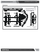
Installation and User’s Guide http://www.orionimages.com DIMENSIONS WBLS 34.57 878.1 0 0 3.94 100 1.58 40.1 2.92 74.1 1.00 25.4 .33 8.3 .13 3.2 .62 15.7 1.11 28.2 1.60 40.7 NOTES: 1. MAXIMUM MOUNTING PATTERN WIDTH IS 30.0"[762mm]. 2. MINIMUM MOUNTING PATTERN WIDTH IS 3.94"[100mm]. 3. MOUNT IS 3.72"[94.4mm] DEEP WHEN FLAT TO WALL. EXTENSION DISTANCE IS 7.0"[177.8mm] WITH A MAXIMUM EXTENSION FROM WALL OF 10.7"[272mm]. FOR RECESSED APPLICATIONS, MINIMUM VERTICAL LIFT 3.72 94.4 2.09 53.2 2.59 65.
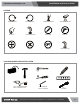
Installation and User’s Guide http://www.orionimages.com LEGEND Tighten Fastener By Hand Loosen Fastener Phillips Screwdriver Hex-Head Wrench Remove Adjust Open-Ended Wrench Pencil Mark Drill Hole Optional Security Wrench TOOLS REQUIRED FOR INSTALLATION #2 7/32" (5.5mm) Wood Stud 5/16" (7.
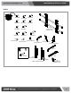
Installation and User’s Guide http://www.orionimages.com PARTS A (8) M4x16mm B (6) M4x20mm D (6) M5x16mm E (6) M5x20mm G (6) M6x16mm H (6) M6x25mm I (6) M8x20mm L (8) .750x.323x.250 J (6) M8x30mm C (6) M4x25mm F (6) M5x25mm R (1) [wall mount] (LSMVU shown) K (4) M8x50mm N (8) M (8) [universal washer] .750x.344x.
Installation and User’s Guide http://www.orionimages.com INSTALLATION WARNING: IMPROPER INSTALLATION CAN LEAD TO MOUNT FALLING CAUSING SEVERE PERSONAL INJURY OR DAMAGE TO EQUIPMENT! It is the installers responsibility to make certain the structure to which the mount is being attached is capable of supporting five times the weight of the WBLS and all attached equipment not to exceed 150 lbs (68 kg).
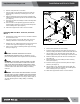
Installation and User’s Guide http://www.orionimages.com 6. Drill one 7/32" pilot hole in each stud. 7. Use two 5/16 x 2-1/2" lag bolts (QC) and two 5/16" flat washers (QB) to attach top of mount (R) to wall. (See Figure 3) 8. Mark the attachment points for the lower mounting slots, making sure the attachment points are located on the studs. (See Figure 3) 9. Drill 7/32" pilot holes at markings for lower mounting holes. (See Figure 3) 10.
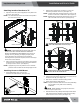
Installation and User’s Guide http://www.orionimages.com Attaching Interface Brackets to TV 2. 1. Align the center of the pull-out uprights (U and V) with center of screen. (See Figure 9) NOTE: Do NOT allow both interface brackets (U and V) to be NOTE: The diamond-shape hole in the bracket corresponds to NOTE: NEVER place both interface brackets (U and V) to one the center of the mount. Adjust Velcro® pull strap (if necessary) so it does not extend beyond bottom of screen.
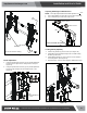
Installation and User’s Guide http://www.orionimages.com Adjusting Roll/Height of Wall Brackets NOTE: The height adjust wall brackets allow adjustment of + 1/2". Top Hook 1. Turn to right (tighten) to raise side of screen (See Figure 14). 2. Turn to left (loosen) to lower side of the screen. 1 Raises screen 2 3 Lowers screen (W) (Screen not shown for clarity) Figure 14 Pullstraps Locking Mount (Optional) 6 (Screen not shown for clarity) Figure 12 Plumb Adjustment 1.
Installation and User’s Guide http://www.orionimages.com USA / Headquarter A P F Europe / UK A 7300 Bolsa Avenue, Westminster CA 92683 714-766-6300 714-766-6310 102 Knightwood Crescent, New Malden, Surrey. KT3 5JW U.K. P +44 (0) 7979-152-943 ORION Images, Corporation. Design, Develop, Manufacture LCD / LED Security Monitors 2011 ORION Images, Corp. All rights reserved www.orionimages.com Asia / Korea A 403-403, Bucheon Technopark 4 Danji Apt.