
User Manual

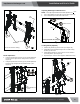

CAUTION: PINCH POINTS! Keep fingers, hands and
cables out of pinch point areas.
6. Pull downward on the pullstraps and swing inward toward
wall, latching interface brackets to lower bar and locking
bottom of screen to the mount. (See Figure 12)
Figure 10
(Y) x 4
Figure 9
Center of bracket
Pull strap
Installation and User’s Guide
http://www.orionimages.com
7300 Bolsa Avenue, Westminster CA 92683 / Tel: 714-766-6300 / Fax: 714-766-6310
8
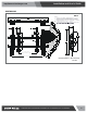
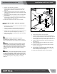
Attaching Interface Brackets to TV
1. Align the center of the pull-out uprights (U and V) with center
of screen. (See Figure 9)
NOTE: The diamond-shape hole in the bracket corresponds to
the center of the mount.
WARNING: IMPROPER INSTALLATION CAN LEAD TO
DISPLAY FALLING CAUSING SERIOUS PERSONAL
INJURY OR DAMAGE TO EQUIPMENT! Using screws of
improper size may damage your display. Properly sized
screws will easily and completely thread into display
mounting holes. If spacers are required, be sure to use longer
screws of the same diameter.
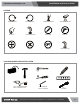
2. Select correct screws, spacers (if necessary) and universal
washers from the hardware bag (A-N) and attach brackets
(U and V) to back of screen. (See Figure 9)
NOTE: Uprights may need to be pulled out to the extended
position in order to install screws through proper holes.
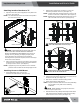
Attaching Screen to Wall Mount
1. Attach wall bracket caps (Y) to top and
bottom of both wall brackets. (See Figure 10)
2. Adjust Velcro® pull strap (if necessary) so it does not
extend beyond bottom of screen. (See Figure 11)
NOTE: Do NOT allow both interface brackets (U and V) to be
located on same side of wall bracket. (See Figure 11)
NOTE: NEVER place both interface brackets (U and V) to one
side of the wall mount center line! (See Figure 11)
Figure 11
Both interface brackets must NEVER be located
to one side of the wall brackets!
Pullstrap
NEVER place both interface brackets to one
side of the wall mount center line (CL)!
Center Line (CL)
3. Hang top hook of interface brackets (U and V) onto the top
bar of the mount (R). (See Figure 12)
4. Slide screen and bars to desired viewing position.
5. Route cables between wall and bars.
NOTE: The pull-out feature allows the screen to be pulled away
from the wall for easy cable access following
installation.