ORO TPMS Manual To ensure correct operation and service please read these instructions before installing and operating the TPMS TABLE of CONTENTS 1. Notice………………………………………………………...…………………1 2. W401A Tire Pressure Monitoring System………………………………….2 3. W401A Tire Pressure Monitoring System Specification………………2 4. W401A Tire Pressure Monitoring system Accessories…………………3 5. W 4 0 1 A S y s t e m I n s ta l l a t i o n … … … … … … … … … … … … … … 3 Display Unit Installation………………………………………………...
NOTICE FCC & E-Mark Notice This device complies with Part 15 of the FCC Rules. Operation is subject to the following two conditions: (1) This device may not cause harmful interference. (2) This device must accept any interference received, including interference that may cause undesired operation. This equipment has been tested and found to comply with the limits for a Class B digital device, pursuant to Part 15 of the FCC Rules.
Caution: the system is wireless RF product; therefore, it may not receive a signal due to the poor environment or incorrect operating either on incorrect installation. When the system continually cannot receive any signal from any tire sensor more than 10 minutes since the system has been switch on for monitoring, the system will shown “ E2 ” and turn on the RED abnormal LED light with alert sound.
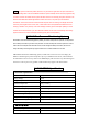
Storage Temperature Range -40℃ to 90 ℃ Operation Temperature Range -30℃ to 85 ℃ Tire Pressure Reading Range 0 ~ 800 kPa Temperature Reading Range -30 ℃ to 100 ℃ Cold-Tire Std. Tire pressure setting range 1.9 ~ 2.8 bar (27 ~ 40 psi; 190 ~ 280 kPa),the factory default is.
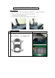
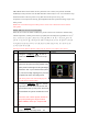
W401A TPMS INSTALLATION 1. Display Installation: 2. a. Firm the magnetic holder in the suitable place. (Suggest place , as shows in the picture) b. Plug in the USB cigarette power cable on the back of display. c. Put the display on the magnetic holder. d. Plug in the power cable to the cigarette lighter power connection. Tire Sensor Installation: Step Operation Process a Take off the 4 tires and mark 1~4 for each tire position. No.4 = Left Front Tire ; No.1 = Right Front Tire。 No.
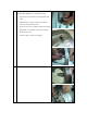
b Take off the tire and bleed the air, then should change to the ORO-TEK TPMS valve, and follow the steps: 1. Snap in the valve from the internal edge side of the wheel. 2. Adjust the valve’s angle, and make the valve be vertical by the edge of the wheel. 3. Put on the circle screw from the outside of the wheel. 4. Tight up the valve with the nylok screw from the outside of the wheel. 5. b Use the 6 angle screwdriver to tight up.
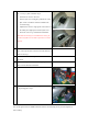
c Put the marked No. 1 tire sensor to the tire which market No. 1. as step a. photo and follow steps: 1. Install the tire sensor to the valve. 2. Use the nylok screw and tight up with the tire sensor. (Pls. use the screwdriver which is included to the accessories bag) 3. Adjust the tire sensor’s angle (paste on the surface of the wheel), then tight up the with the nylok screw. 4. Put on the valve’s cap, and finish the installation. When there is necessary to re-install the tire sensor, pls.
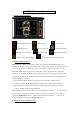
W401A Systems Operation 1. Display Signals Description: :Bad Transmission Signal。 :Tire deflating signal。 :Low Battery on Tire Sensor。 :Abnormal Tire Condition Signal。 2.
ORO TEK W-401A exists 4 modes of factory default for user to choose, the parameter should be modified by formal procedure. Press the SET UP button continuously for 2 sec. to be entered the set up mode from Front tire-Std. tire pressure set up, Rear Tire-Std. tire pressure set up, Tire Temperature-Over Temperature Warning, Operating Mode and others parameters setting, and pls. refer below process: NOTE: The user should change the suitable pressure unit for own vehicle before entered into the setting mode.
system will automatically enter the Rear tire Low pressure set up mode. Rear Tire-Low Tire Pressure Setting Mode Setp Operating Process a Photograph The system will enter the Rear Tire low pressure set up mode automatically after set up the Front Tire Low Pressure set up mode. b The wireless receiver and display unit will now show the low tire pressure factory default value (2.3bar) shown in blue light and the yellow light indicates the ”bar”.
b The display shows on the figure is the tires factory default high temperature value (80oC) for the tires in blue. If there is no modification to the user, then press the Set Up button to enter the next set up mode. NOTE: If the unit is ℉ the number will be flashing in 176. c to change the high Press the function key temperature figure, the unit will add 1 ℃ by each pressing, the range for temperature set up are between 60℃~99℃, the system will return back to 60℃ after 99℃.
c Press the Mode button, will enter to the temperature display mode as the picture on the right hand side, and the unit for temperature is ℃. NOTE: The system may use other unit for pressure by ℃、℉ , depending the system for different area of the world. d Press the Mode button, will enter to the Tire Pressure~ temperature by rotation mode. And the battery voltage will display permanently.
warning when the tire figure displayed in RED. 2 Warning Situation: When the temperature is higher than set up unit. (Factory default is 80℃ and 176℉ Warning Method: Will sound Beep Beep as warning when the tire figure displayed in RED. 3 Warning Situation: When the tire pressure is deflating rapidly. Warning Method: When the tire figure flashing in RED with deflating rapidly signal by Beep Beep warning sound. 4 Warning Situation: When the battery voltage is below than set up unit.
6 Warning Situation: When the Monitor run out of initial setting up by factory default. Warning Method: The four display unit will show by E1 and not lighting on four tires figures. 7 Warning Situation: When Monitor sensor can not receive one of the tire sensor, over than 9 min.. Warning Method: The failure tire sensor will show by E2 without light on tire figure. 8 Warning Situation: When the tire sensor got failure on factory default.
Description for each set up process Mode 1: Front and Rear tire exchange FRONT No. 4 No. 1 No. 3 No. 2 The monitor will show up as below photograph, the NO. 1 which shows in yellow means the mode 1, and the 4 red lights means the tire position before reset as shows in pic. 1, the 4 green lights means the mode 1 has been completed set up. Press the Set Up button continuously for 2 sec. until sounds Beep which means has accomplished the set up for mode 1. (Front and Rear Tires Exchange) Pic. 1 Pic.
Pic. 1 Pic. 2 模式 3:Front Tire Diagonal exchange, Rear Tire parallel change to the front FRONT No 4 No 1 No 3 No 2 The monitor will show up as below photograph (Pic. 1 and Pic 2), the No. 3 in yellow means in mode 3. and the 4 red lights means the tire position before reset as shows in pic. 1, the 4 green lights means the mode 3 has been completed set up. Press the Set Up button continuously for 2 sec. until sounds Beep which means has accomplished the set up for mode 3.
1. Set up for RF tire sensor: The display will flash green and red with No. 1 which means the RF tire can be proceed for the set up as below pic. 1, by the meantime the user should deflate the tire pressure rapidly over than 0.3bar/30kPa or 4 Psi in 15 sec. until sounds Beep, which means the user is completed the set up for RF tire as shows on below pic. 2. If there is no need to set up the RF tire sensor, just press the Set Up mode button to jump over this process. Pic 1 Pic 2 2.
Pic 1 Pic 2 4. Set up for LF tire sensor The display will flash green and red in tire figure and No. 4 which means the LF tire can be proceed for the set up as below pic. 1, by the meantime the user should deflate the tire pressure rapidly over than 0.3bar/30kPa or 4 Psi in 15 sec. until sounds Beep, which means the user is completed the set up for LF tire as shows on below pic. . then the systems will enter back to the normal operating display.
Pic 1 Pic 2 2. Set up for RR tire sensor The display will flash green and red in tire figure and No. 2 which means the RR tire can be proceed for the set up as below pic. 1, by the meantime the user should deflate the tire pressure rapidly over than 0.3bar/30kPa or 4 Psi in 15 sec. until sounds Beep, which means the user is completed the set up for RR tire as shows on below pic. 2. then the systems will enter to the LR tire sensor set up mode. Pic 1 Pic 2 3. Set up for LR tire sensor.
Pic 1 Pic 2 4. Set up for LF tire sensor The display will flash green and red in tire figure and No. 4 which means the LF tire can be proceed for the set up as below pic. 1, by the meantime the user should deflate the tire pressure rapidly over than 0.3bar/30kPa or 4 Psi in 15 sec. until sounds Beep, which means the user is completed the set up for LF tire as shows on below pic. . then the systems will enter back to the normal operating display, without any changing.
All implied warranties, including the warranty of merchantability, are limited to this same ninety-day period from date of original purchase. We are not liable for any direct or consequential loss or property damage arising from any use of this product. This warranty gives you specific legal rights, and you may also have other rights, which vary from state to state. This does not affect your statutory rights.
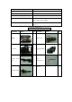
50 7 0.5 250 37 2.5 450 66 4.5 60 9 0.6 260 38 2.6 460 67 4.6 70 10 0.7 270 39 2.7 470 69 4.7 80 12 0.8 280 41 2.8 480 70 4.8 90 13 0.9 290 42 2.9 490 72 4.9 100 15 1.0 300 44 3.0 500 73 5.0 110 16 1.1 310 45 3.1 120 18 1.2 320 47 3.2 130 19 1.3 330 48 3.3 140 20 1.4 340 50 3.4 150 22 1.5 350 51 3.5 160 23 1.6 360 53 3.6 170 25 1.7 370 54 3.7 180 26 1.8 380 55 3.8 190 28 1.9 390 57 3.9 200 29 2.