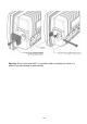
Warning: Do not mount the NAV-7 in a position where sea spray can reach it, or where it may be exposed to direct sunlight 23
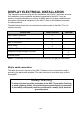
DISPLAY ELECTRICAL INSTALLATION This manual is concerned only with the installation of the NAV-7 and does not cover the installation of any peripheral equipment connected to the NAV-7 such as printers, navigational systems or source of NMEA data. For proper installation and connection of peripheral equipment to the NAV-7 refer to the installation manuals for these products. The table below shows the connections that must be made to the NAV-7 for it to function correctly.
12V or 24 V DC power connection A connection must be made to a 12 or 24 V DC supply via a circuit breaker capable of supplying at least 2 amps. Connection should be to the ship’s radio battery and be in accordance with GMDSS requirements. • Connections should be made using the 2 m power cable provided • Use cable ties to restrain the wiring, and so prevent it becoming weakened by vibration.
Signal line termination RS422 signal lines may need termination resistors at the far end of the serial cable connected to the NAV-7, depending on the length of connecting cable and the rate of data transmission. Both the IBS and the NMEA ports in the NAV-7 have inbuilt 100O termination resistors for both Tx and Rx. Whether termination is required depends on many factors, particularly the length of the signal cable and the environment in which the equipment is operating.
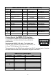
Power, Alarm & IBS port Pin Number 1 Connection (2m cable supplied) NAV-7 Cable Colour Notes IBS_TXA O/P WHITE/BLUE O/P to IBS port 3 +V (12/24 V DC nominal) I/P RED/BLUE Ship’s supply +ve 4 -V (0V) I/P BLUE/RED Ship’s supply -ve IBS_TXB O/P BLUE/WHITE O/P to IBS port 8 AUX_NC O/P ORANGE/WHITE Alarm Relay NC 9 AUX_NO O/P WHITE/BROWN 10 AUX_COM O/P WHITE/GREY 12 IBS_RXB I/P GREEN/WHITE I/P from IBS port 13 IBS_RXA I/P WHITE/GREEN I/P from IBS port 2 5 6 7 Alarm
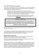
Alarm relay The NAV-7 provides a relay connection which can be selected as normally closed or normally open contacts. The alarm relay function is configurable from within the setup pages and can be set (for example) to switch (change state) on receipt of a Search and Rescue message or for a system fault. The red LED on the front panel of the NAV-7 mirrors the function of the alarm relay.
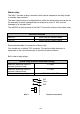
Connector pin-outs NAV-7 rear panel connections: TNC RF connector /8” Spade terminal – ground pin 9-way D-type – NMEA 0183 & printer port USB connector – for in-field programming 15-way D-type – power and IBS port and alarm relay 1 • The auxiliary alarm contact is capable of switching up to 24 V DC at up to 1 A (inductive load). The contacts are not connected to any internal voltages. • The power supply input is isolated from the case and antenna. It must remain within the range 10.8 – 31.
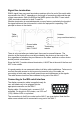
ANTENNA INSTALLATION Selecting a suitable antenna The NAV-7 receives transmissions on three frequencies. 518 kHz transmissions are in International English; 490 kHz and 4209.5 kHz transmissions may be in a local language. To receive on all frequencies the NAV-7 must be used with a wide frequency (400kHz to 5MHz) antenna that covers 518 kHz, 490 kHz and 4209.5 kHz. If you have purchased the NAV-7 receiver without an antenna then a suitable active NAVTEX antenna should be used.
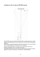
Important NAVTEX antennas must be mounted clear of obstructions and at least 0.5 metres away from other antennas. Where practical avoid locating the NAVTEX antenna close to MF / HF transmitting antennas or VHF / AIS antennas. Ensure that antennas cannot be snagged by mooring warps or running rigging or engulfed by green water. Antennas should always be mounted vertically.
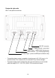
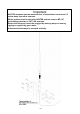
Installation of the tri-channel NAVTEX antenna The NAVTEX antenna should be mounted vertically, in an elevated position. Metal, rigging or other antennas must not be located in the 'NO GO cone' surrounding the upper part. Use the mounting bracket supplied; an alternative mounting kit may be purchased if the mounting arrangement is unsuitable for your installation. Attach the clamping brackets to the antenna mounting adapter and use the clamping arrangement to fix to a suitable vertical tube.
Slide the rubber boot over the PL259 connector; if desired, it may be filled with silicone grease for a better weatherproof seal. Screw the antenna down into the antenna mounting adapter. Ensure that the mounting adapter is connected to ground. If necessary, connect a grounding wire, 2.5 mm2 minimum, to a suitable ground point. Installation of the antenna cable Start routing the antenna cable at the antenna end. Where the cable passes through bulkheads or decks, waterproof deck glands should be installed.
Extending the antenna coax cable If required, the coaxial cable may be extended with 50 ohm coaxial cable and connectors. The maximum cable length should not exceed 100 m. Ensure that any cable joints are well secured and waterproofed using self-amalgamating (rubber) tape. Cable should be RG-58 / RG-67 / RG-213 / RG-214 grade or better; connectors should be suitable RF types (TNC, BNC, etc).
Testing the Banten active antenna If it is suspected that reception is being compromised by the antenna performance, the antenna should be checked for electrical damage. Disconnect the antenna from the NAV-7 by unscrewing the TNC connector at the back of the NAV-7. Using a DVM set on resistance, measure across the TNC RF connector from the centre pin to the outer ferrule, looking back up towards the antenna. DO NOT ATTEMPT TO MEASURE THE RESISTANCE OF THE TNC SOCKET ON THE NAV-7.
OPTIONAL POWER SUPPLY UNIT 89-029 Consult the installation instructions packed with the power supply. An additional ground wire may be connected between the green safety earth wire on the NAV-7 and the ground terminal on the NAVTEX Power Supply Unit. Dimensions and drilling plan Technical specification Power supply wiring 2 110 V AC 1.6 A 110 V AC 2 x 1.5 mm 230 V AC 0.8 A 230 V AC 2 x 0.7 mm 24 V DC 7.0 A 24 V DC 2 x 6.
Maintenance Guide General Points to Check • Periodically make sure that the antenna connector is well sealed and that there isn’t sign of corrosion around the PL259 connector • Make sure connections to the back of the NAV-7 display are secure Cleaning Instructions • Periodically clean the LCD front window with a soft lint-free cloth (such as those supplied by opticians to clean spectacles) • Do not used cleaning solvents on any part of the NAV-7 Disposal at end of life At the end of its life dispose of
TROUBLESHOOTING GUIDE General Points to Check • Make sure that the antenna is mounted vertically, and is sited clear of obstructions • Make sure the vessel is operating within the coverage area of a NAVTEX transmitter • When the NAVTEX station(s) selected are transmitting, icons for 490, 518 and 4209.
The NAV-7 is not receiving 1 Are you within range of a NAVTEX transmitting station? 2 Has there been a scheduled transmission since the NAV-7 was first switched on? 3 Check that the antenna is clear of obstructions and has not suffered external damage 4 Check that the antenna cable is not damaged 5 Check that the antenna fault icon is not being displayed on the status bar at the top of the display 6 From within the setup screens, check that the NAVTEX transmitting stations and message categories are correct
SPECIFICATIONS Complies with technical standards: IMO Resolutions MSC.148(77) A.2.1, A694 (17) MEA 0183 / Printer Serial Interface 9 way D-type SOLAS Regulation IV/7.1.4 Conforms to IEC 61162-1 ITU-R M.540-2, ITU-R M.
Appendix I: NAVTEX station database 518kHz NAVTEX stations Id A A A A A A A A B B B B B B B B C C C C C C C C C D D D D Area 15 09 02 11 04 03 01 13 11 09 04 01 13 03 15 07 07 08 01 03 13 12 04 11 15 02 01 03 13 Country Chile Iran France Indonesia USA Russia Norway Russia Indonesia Bahrain Bermuda Norway Russia Ukraine Chile Namibia South Africa Mauritius Russia Ukraine Russia USA Canada Singapore Chile Spain Sweden Turkey Russia Name Antofagusta Bushehr Corsen Jayapura Miami Novorossiysk Svalbard Vladi
Id D D D D E E E E E E F F F F F F F F F G G G G G G G H H H Area 12 15 04 11 13 11 15 01 03 12 03 01 09 04 02 15 11 06 13 01 09 15 08 11 04 02 15 01 06 H H H H H I I 03 09 11 04 12 03 02 I I I J J J J J J K K K L L L L M M M M M M N N N 07 15 11 01 12 11 04 15 03 03 11 01 11 03 15 01 02 03 09 01 11 06 03 11 01 Country Canada Chile Canada Indonesia Russia Indonesia Chile UK Turkey USA Turkey Russia Iran USA Acores Chile Thailand Uruguay Russia UK Saudi Arabia Chile India Japan USA Spain Chile Sweden D
Id N N O O O O Area 04 06 06 07 11 12 O O O P P P P P P P P P P P Q Q Q Q Q Q R R R R R R R S S S T T T T U U U U U V V V V 03 01 04 06 11 03 01 09 11 11 11 08 11 04 12 01 06 11 03 04 06 11 02 01 04 03 12 04 11 16 03 04 11 01 16 04 11 01 03 03 11 04 11 V W W W W W W W X X X X 01 12 11 04 03 16 11 01 11 12 04 09 Country USA Argentina Argentina South Africa China Hawaiian Islands Malta UK Canada Argentina Vietnam Israel Netherlands Pakistan Taiwan Taiwan Taiwan India Taiwan Canada USA Ireland Argentina
Id X Area 03 Country Spain Name Valencia Latitude 38°43’ N Longitude 0°9’ E Range (NM) 300 Latitude 54°51’ N 50°35’ N 64°05’ N 50°35’ N 55°02’ N 48°28’ N 38°44’ N 38°32’ N 41°17’ N 41°04’ N 38°21’ N 36°53’ N 44°06’ N 43°06’ N 50°11’ N 46°11’ N 63°44’ N 43°44’ N 37°03’ N 35°36’ N 23°33’ N 23°54’ N Longitude 05°07’ W 01°18’ W 21°51’ W 01°18’ W 01°26’ W 05°03’ E 09°11’ W 28°38’ W 36°20’ E 28°56’ E 26°35’ E 30°42’ E 28°37’ E 05°59’ E 66°06’ W 59°54’ W 68°33’ W 66°07’ W 129°26’ E 126°29’ E 119°38’ E 121°
Appendix II: Message type indicators NAVTEX broadcasts use following message type letter: A B C D E F G H I J L V W X Y Z Navigational warnings Meteorological warnings Ice reports Search and rescue information, and pirate warnings Meteorological forecasts Pilot service messages DECCA messages LORAN messages OMEGA messages (Note: OMEGA has been discontinued) SATNAV messages (i.e. GPS or GLONASS) Navigational warnings - additional to letter A Notice to Fishermen (U.S. only) Environmental (U.S.
Appendix III: Declaration of Conformity 46
McMurdo Limited Product Warranty Subject to the provisions set out below McMurdo Limited warrants that this product will be free of defects in materials and workmanship for a period of 24 months from the date of purchase.
McMurdo Limited Silver Point Airport Service Road Portsmouth PO3 5PB United Kingdom Tel: +44 (0)23 9262 3900 Fax: +44 (0)23 9262 3998 www mcmurdo.co.uk Email: sales@mcmurdo.co.