
Installation & Assembly_1
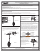

Package Contents
1of2
Assembly Instruction Sheet #IS-PCIN1504C
For Style PCIN1504C
Crossbar
x1
A
C
Mounting Screw
x2
B
Fixture Body
x1
2016 QuoizelInc.
ReleasedDate:2016-08-16
Thank you for purchasing a Quoizel product.
Need assistance with parts or assembly? Call Quoizel customer service at 1-800-645-3184
or visit us on-line at www.quoizel.com
Warnings and Cautions
Turn off electricity at circuit breaker or main fuse box before installation. Consult a licensed electrician if in doubt.
These instructions are provided for your safety. It is very important you read them completely before installing the fixture. We strongly
recommend that a licensed, professional electrician perform the installation.
Pleasegoto forproductcleaningtips.Gotothe selection.
Flatheadscrewdriver,Phillipsscrewdriver,pliers,wirecutters,wirestrippers,electricaltape,safetyglasses.
Integrated4.5WLED
:LutronDVELV-300PorLutronSELV-300P.
www.quoizel.com Care+Maintenance
ToolsRequired:
LightSource:
CompatibleDimmerSwitches
EstimatedAssemblyTime:
Preparation:
20-30minutes
Identifyandinspectallpartsbeforebeginninginstallation.Checkpackagecontentlistanddiagramsbelowtobesureallpartsare
present.Ifanypartsaremissingordamaged,donotattempttoassemble,install,oroperatethefixture.Contactcustomerserviceforreplacement
parts.
STEP 1 Adjust Fixture Height-
A. Push the Pin on the bottom of the Ceiling Canopy, adjust the Cable
in or out of the Ceiling Canopy to achieve your desired hanging
height. Once your desired hanging height is achieved, release the
pin and move the Slider close to hex nut inside of the Ceiling
Canopy.
Ceiling
Canopy
Cord
Slider
Pin
Cord
Ceiling
Canopy
Figure 1
C
STEP 2 Attach Crossbar to Outlet
Box
-
A. Attach the Crossbar (A) to Outlet Box
and secure by threading Outlet Box
Screws (not supplied) into the
Mounting Holes on the Outlet Box.
Tighten until snug.
A
Outlet
Box
Outlet Box
Screw
Figure 2
STEP 3 Make Wire Connections-
Use standard wire connectors (not included) to make all wire
connections. Twist connectors until wires are tightly joined together.
Wrap each connection with approved electrical tape and carefully
stuff all the connected wires into the Outlet Box.
: If the electrical wire is going to be cut shorter than provided.
Please leave approximately 10” of wire extruding from the Ceiling
Canopy. You will need to identify the "L" line wire and the "N" wire
before you cut the excess wire off. One is labeled N and the other
labeled L. To do this strip back the clear wire covering the 2 fixture
wires as far as you need to. This will expose each fixture wire
individually. Separate the "L" wire from the other one and re-label
the wire near where you want to make the cut. Be sure to mark the
wire on the side of the fixture and not on the excess wire being cut
and removed. Do the same labeling with the "N" wire.
A.
Note
Wire Labeled
“N" from fixture
Wire Labeled
"L" from fixture
Ground wire
from fixture
White wire
from supply
Black wire from
supply (or Red)
Ground wire
from supply
Figure 3
STEP 4 - Attach Ceiling Canopy to
Crossbar
A. F
. Line
up the holes on the side of the
eiling anopy to the mounting
holes on the Crossbar (A). Secure
them with Mounting Screws (B).
Tighten until sung.
it excess cord and electrical wires
in the ceiling canopy properly
cc
Your fixture is now assembled and
ready to use. Enjoy!
Figure 4
A
B
Ceiling
Canopy
C