
Assembly Instruction
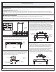

Package Contents
1of2
Assembly Instruction
B
Fixture
Body
x1
Crossbar
x1
Assembly
A
Flatheadscrewdriver,Phillipsscrewdriver,pliers,wirecutters,wirestrippers,electricaltape,safetyglasses.
LED24W
:LutronDVELV-300PorLutronSELV-300P.
ToolsRequired:
LightSource:
CompatibleDimmerSwitches
EstimatedAssemblyTime:
Preparation:
20-30minutes
Identifyandinspectallpartsbeforebeginninginstallation.Checkpackagecontentlistanddiagramsbelowtobesureallpartsare
present.Ifanypartsaremissingordamaged,donotattempttoassemble,install,oroperatethefixture.Contactcustomerserviceforreplacement
parts.
Warnings and Cautions
Turn off electricity at circuit breaker or main fuse box before installation. Consult a licensed electrician if in doubt.
These instructions are provided for your safety. It is very important you read them completely before installing the fixture. We strongly
recommend that a licensed, professional electrician perform the installation.
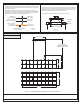
STEP 1 Adjust the Fixture Body Height-
A. Push the pin on the bottom of the ceiling canopy adjust the cable
length to achieve your desired fixture height. Move the Slider on the
cable next to the hex nut inside of the ceiling canopy.
Figure 1
Ceiling
Canopy
Slider
Pin
LED DRIVERLED DRIVER
STEP 2 Install Crossbar Assembly-
A. Pass the supply wires with ground wire through Crossbar Assembly
(A). Attach Crossbar Assembly (A) to the Outlet Box with the head of
the Green Ground Screw facing you. Secure it with Outlet Box
Screws (not included). Tighten until snug.
Supply Wires
with Ground Wire
A
Outlet Box Screws
(not included)
Outlet Box
Figure 2
STEP 3 Test Fitting Ceiling Canopy to Crossbar Assembly-
A. Remove mounting balls from Crossbar Assembly (A). Fit the ceiling
canopy and Fixture Body (B) to Crossbar Assembly (A) and secure
with mounting balls. Note: The ceiling canopy should be snug
against the ceiling and the mounting balls. If Not, adjust the length of
the mounting screw on the Crossbar Assembly (A) by unscrewing
the preassembled hex nut and lock washer and then screwing the
mounting screws in or out of the crossbar until the correct length is
achieved. Once the ceiling canopy and Fixture Body (B) is secure,
remove the mounting ball and ceiling canopy and Fixture Body (B)
and proceed to Step 4.
Figure 3
STEP 4 - Attach Lanyard
A. The purpose of the lanyard is to provide the installer a means to
support the fixture from the junction box while connecting the
electrical wires. This enables the fixture to hang from the junction
box and your hands are free to make the wire connections.
B. Turn the Button Stop so it may be inserted into the Inner Backplate
slot. Make sure the Button Stop is completely inside the Inner
Backplate (A). Slowly release the fixture to make sure it is
supported by the Button Stop. Proceed to the wiring steps in the
next step. Once you are complete with the wiring there is nothing to
do with Lanyard. The Lanyard will push into the junction box when
the fixture is placed for final mounting.
Button Stop
Lanyard
Slot
A
Ceiling
Canopy
Figure 4
Mounting Screw
A
Hex Nut and
Lock Washer
Mounting Ball
Ceiling
Canopy
Thank you for purchasing a product.