
Assembly Instruction

Integrated8WLED
:LutronDVELV-300PorLutronSELV-300P.
LightSource:
CompatibleDimmerSwitches
ToolsRequired:Flatheadscrewdriver, Phillips screwdriver,pliers,wirecutters,wirestrippers,electricaltape,safetyglasses.
EstimatedAssemblyTime:
Preparation:
20-30minutes
Identifyandinspectallpartsbeforebeginninginstallation.Checkpackagecontentlistanddiagramsbelowtobesureallpartsare
present.Ifanypartsaremissingordamaged,donotattempttoassemble,install,oroperatethefixture.Contactcustomerserviceforreplacement
parts.
Warnings and Cautions
1of2
Assembly Instruction
Turn off electricity at circuit breaker or main fuse box before installation. Consult a licensed electrician if in doubt.
These instructions are provided for your safety. It is very important you read them completely before installing the fixture. We strongly
recommend that a licensed, professional electrician perform the installation.
Disconnect fixture from power source before replacing bulbs. Make sure bulbs are given sufficient time to cool before removal. Do not subject
glass parts to any shock while in operation or shattering may result.
Package Contents
B
Mounting
Screw
x2
Inner
Backplate
x1
A
C
Fixture
Body
x1
E
Glass B
x1
G
Shade Holder
x2
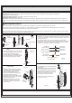
STEP 2 Install Inner Backplate and
Fixture Body
-
A. Pass the supply wires through Inner
Backplate (A). Attach Inner Backplate
(A) to Outlet Box with the head of
Green Ground Screw facing you.
Secure it with Outlet Box Screws (not
included). Tighten until snug
B. Race all supply wires through the Inner
Backplate (A) as shown. Refer to Step
3 for wiring connections.
C. Attach Fixture Body (C) over Inner
Backplate (A) and secure with Lock
Screws (B). Tighten until snug with
screwdrivers.
.
A
Figure 2
Outlet
Box
Outlet Box
Screw
B
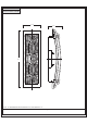
STEP 4 Install Glass to Fixture Body-
A. Insert Glass (E/D) into the Shade Holder
(G) properly.
B. Place Shade Holder (G) over the top of
the Fixture Body (C), line up the hole on
the Shade Holder (G) and the mounting
hole on the Fixture Body (C), secure by
threading Lock Screw (F) into the
mounting hole, tighten until sung.
Your fixture is now assembled and
ready to use. Enjoy!
F
Lock
Screw
x4
D
Glass A
x1
STEP 1 Install Shade to Fixture
Body
- Holder
A. Place Shade Holder (G) over the bottom
of the Fixture Body (C), line up the hole
on the Shade Holder (G) and the
mounting hole on the Fixture Body (C),
secure by threading Lock Screw (F) into
the mounting hole, tighten until sung.
F
C
G
Figure 1
F
G
C
D
E
STEP 3 - Wire Connections
A. Wrap bare or green ground wire around green ground screw on the
crossbar, no less than 2 inches from the end of the wire. Tighten the
green ground screw.
B. Use standard wire connectors (not included) to make all wire
connections. Twist connectors until wires are tightly joined together.
Wrap each connection with approved electrical tape and carefully
stuff all the connected wires into the Outlet Box.
Figure 3
Green Ground Screw
on the Crossbar
White wire
from outlet box
White wire
from fixture
Black wire from
outlet box (or Red)
Black wire
from fixture
Bare, or Green
Ground wire
from outlet box
Ground wire
from Fixture
Figure 4
Thank you forpurchasing a product.