
Assembly & Installation Instructions

ASSEMBLY AND INSTALLATION
INSTRUCTIONS
NOTES: 1. Before installing, consult local electrical codes for wiring and grounding requirements.
2. READ AND SAVE THESE INSTRUCTIONS.
WARNING:
TO AVOID RISK OF ELECTRICAL SHOCK, BE SURE TO SHUT OFF
POWER BEFORE INSTALLING OR SERVICING THIS FIXTURE.
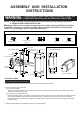
Hardware Package (included):
Turn off the power at fuse or circuit box.
Installation Steps
Mounting Screw (A)
Mounting Plate
Fixture Mounting Screw
Dry Wall Screw (E)
Mounting Screw (A)
Vertical Installation
Two methods of installation:
Horizontal Installation
Fixture
Wire Nut (C)
Green Grounding
Screw (B)
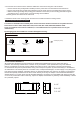
1. Remove two fixture mounting screws to separate the mounting plate from fixture.
2. Fix the mounting plate to the wall.
a) For wooden material:
Attach the mounting plate to the outlet box by using two mounting screws, and then secure the dry wall screws
through the set holes to the wall.
b) For cement and drywall materials :
Hold the mounting plate to the outlet box and mark the outermost set holes on the wall surface for drilling. Remove
the mounting plate from the outlet box. Drill both set holes. Thread the anchors into the holes, then attach the
mounting plate to the outlet box by using two mounting screws. Secure the dry wall screws through the set holes
into the anchors.
3.
Attach mounting plate to the outlet box using two mounting screws.
Warning: LED electronics can be damaged by electro static discharge (ESD)shock. Before
installation, discharge yourself by touching a grounded bare metal surface to remove this
hazard. To avoid damage, do not touch the LED module.
Anchor (D)
Outlet Box
Green Grounding Screw (B)
Wire Nut (C)
Anchor (D)
Dry Wall Screw (E)