
Assembly Instructions


40 | iASSIST 2-Pod Version Surgical Technique
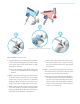
6. Disconnect the Tibial Aligner by grasping the
instrument by the grip and pulling it up and away
from the Tibial Adjustment Mechanism.
7. Loosen the blue knob on the distal part of the
Tibial Alignment Guide.
8. Position the rod of the Tibial Alignment Guide to an
initial starting orientation per the preset position (L
or R) on the distal part of the Tibial Alignment Guide.
For a left knee procedure, the preset position is L.
For a right knee procedure, the preset position
is R.
Tibial Workow Selection (cont)
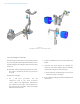
5. Use three 3.5 x 38 mm Hex Head Screw to secure
the Tibial Adjustment Mechanism to the bone, by
rst securing screws in the medial hole, secondly
in the upper lateral hole and nally in the lower
lateral hole.
Warning: Control the speed of the power tool
or nish xating the screws manually to avoid
stripping the cortex of the tibia. As provided by
Zimmer, the 500 RPM adaptor of the Zimmer
Universal Power System Surgical Instruments
can be used to secure screws. From registration
to validation, the instruments must remain
stable and properly xated to the bone to
ensure accuracy of the system.
Figure 3.6.2
Tibial Aligner Technique- Tibial Workow Selection