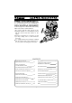
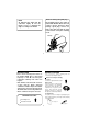
It is of vital importance, before attempting to operate your engine, to read the general 'SAFETY INSTRUCTIONS AND WARNINGS' section on pages 2-5 of this booklet and to strictly adhere to the advice contained therein. Also, please study the entire contents of this instruction manual, so as to familiarize yourself with the controls and other features of the engine. Keep these instructions in a safe place so that you may readily refer to them whenever necessary.
SAFETY INSTRUCTIONS AND WARNINGS ABOUT YOUR O.S. ENGINE Remember that your engine is not a "toy", but a highly efficient internalcombustion machine whose power is capable of harming you, or others, if it is misused. As owner, you, alone, are responsible for the safe operation of your engine, so act with discretion and care at all times. If at some future date, your O.S. engine is acquired by another person, we would respectfully request that these instructions are also passed on to its new owner.
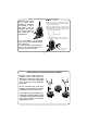
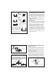
! • NOTES • After starting the engine, carry out any needle- These engine were designed for model helicopters. Do not attempt to use it for any other purpose. valve readjustments after stopping the rotor by closing the throttle to the lowest r.p.m.. Stop the engine before attempting to make other adjustments to the carburetor. • Mount the engine in your model securely, following the manufacturers' recommendations, using appropriate screws and locknuts. • Use an electric starter.
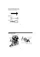
Notes on installing cooling fan and clutch Application is as follows: Remove the crankcase rear cover plate from the engine and rotate the crankshaft to the bottom dead center (BDC) position. Do not use a tool which locks piston when installing a cooling-fan and clutch, or top of the piston may be damaged. Also, do not insert a screw driver or the similar into the exhaust port.
Note on heating the glow plug NOTE As delivered, the engine has the carburetor lightly fit into the intake. Secure it changing the angle according to the model. The heatsink head on the engine is treated with Alumite which does not conduct current. Therefore, when heating a glow plug, connect one lead to the glow plug and the other to the head of cover plate retaining screw.
Fuel Select, by practical tests, the most suitable fuel from among the best quality fuels available in your country for helicopter use. For the best throttle response, a fuel containing 10% to 30% nitromethane is preferable. Lubricants may be either castor-oil or a suitable synthetic oil (or . a blend of both) provided that they are always of top quality. For consistent performance and long engine life, it is essential to use fuel containing AT LEAST 18% lubricant by volume.
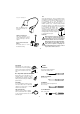
LONG SOCKET WRENCH WITH PLUG GRIP Recommended for easy removal and replacement of the angled and recessed glowplug, the O.S.Long Socket Wrench incorporates a special grip. 8mm End Wrenches 8mm, 13mm, 14mm, etc. Needle Nose Pliers 12 ENGINE PARTS NAME Heatsink Head Glowplug Mixture Control Valve Carburetor Typr 60LH Fuel Inlet (No.
FACTS ABOUT GLOWPLUGS Since the compatibility of glowplug and fuel may have a marked effect on performance and reliability, it may be worthwhile to choose the R/C type plug found most suitable after tests. Recommended O.S. plugs are No.8, A5 and A3. Carefully install plug finger-tight, before final tightening with the correct size plug wrench. However, plug life can be extended and engine performance maintained by careful use, i.e.: Install a plug suitable for the engine.
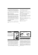
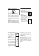
CORRECT CARBURETOR CONTROLS With a fixed-wing model, power failure is rarely a serious threat to the safety of the aircraft since it can usually glide down to a safe landing. In a helicopter, on the other hand, it is vitally imporant that the engine keeps running and that there is a quick and reliable response to the throttle in order to ensure safe ascent and descent of the model. Front view Side view Top surfaces are in the same plane. INCORRECT Two adjustable controls are provided on this carburetor.
Graduations on the carburetor body STARTING Be sure to use a muffler pressurized fuel feed. Use the same fuel as you intend to employ for actual operation of your model. Fully opened position 1. Opening and closing of the Needle-Valve Turn the needle clockwise to close the needle-valve, and turn the needle counter-clockwise to open the needle-valve as shown in the sketch. Fully closed position Carburetor Body Carburetor Rotor As shown in the sketch, the carburetor has graduation marks.
NOTE: If the throttle response is poor or the engine stops due to a temporarily over-rich mixture immediately after the engine is started, pinch the fuel line for one or two seconds until the engine r.p.m. increase and the engine runs steadily. RUNNING-IN ("Breaking-in") All internal-combustion engines benefit, to some degree, from extra care when they are run for the first few times ー known as running-in or breaking-in. This is allows the working parts to mate together under load at operating temperature.
H Hover the model and actuate the throttle to observe response over the medium speed range. lf the engine smokes excessiveIy and throttle response is poor, the mixture is too rich ; in which case, land the model and turn the Needle Valve clockwise. Do not close the NeedIe Valve too much, keeping it a little on the rich side at this stage. D lf, at this time, the engine is slow to pick up and produces an excess of exhaust smoke, the mixture is too rich.
SUBSEQUENT READJUSTMENTS CARBURETOR CLEANLINESS Once the engine has been run-in and the carburetor controls properly set up, it should be unnecessary to alter the mixture settings, except to make minor adjustments to the Needle Valve occasionally, to take account of variations in climatic conditions.
ADJUSTING CHART A Open the Needle Valve 1.5 turns from the fully closed position. Make sure that the Mixture Control Valve is at the factory setting.
INSTALLATION OF THROTTLE SERVO After the engine is installed in the helicopter, please observe the following recommendations when linking the throttle servo to the carburetor. Servo output arm Throttle arm Locate the servo so that its output arm and the throttle pushrod are, as close as possible, directly in line with carburetor's throttle arm, as shown. Throttle control rod A and B should be equal of length.
Symptom TROUBLE SHOOTING Engine fails to fire. Corrective action Cause Fuel tank is empty. Fuel not reaching the engine. Fill the tank with fuel and repeat Priming procedure. Glowplug element is burnt out. Glowplug battery discharged Replace glowplug. Recharge or replace the battery. Clogged fuel filter Silencer inside is dirty. Clean or replace fuel filter. Clean inside silencer. Over priming Remove glowplug and pump excess fuel. Fuel tubing is disconnected.
Symptom Unstable idle Corrective action Cause Unsuitable glowplug Use suggested glowplug in the instructions. Unsuitable fuel Do not use extremely high nitro or low oil fuel. Silencer is disconnected or has play Install silencer securely. Symptom Not reaching expected peak r.p.m. Corrective action Cause Insufficient warming up or running-in. Set the needle only after warming up. Complete running-in. Silencer or manifold is not securely connected or disconnected.
ENGINE EXPLODED VIEW ENGINE PARTS LIST C.M3x15 1 18 2 16 3 32 5 33 4 6 7 C.M3x8 17 8 15 No. Code No. 1 2 3 4 5 6 7 8 9 10 11 12 13 14 15 16 17 18 25204200 25203100 25303400 25203200 25206000 25217000 25205000 29083020 23210007 46120000 26731002 23981700 25201000 26730010 25202000 25214000 25207000 25613000 71608001 Description Hyper Head Cylinder Liner Piston Ring Piston Piston Pin Piston Pin Retainer (2pcs.
CARBURETOR EXPLODED VIEW C.M3X8 1-1 2 1 4 6 9 9-3 3-3 5 7 9-4 9-1 9-2 10 11 *Type of screw C…Cap Screw M…Oval Fillister-Head Screw F…Flat Head Screw N…Round Head Screw S…Set Screw 8 3-2 3-1 3 34 CARBURETOR PARTS LIST No. Code No.
O.S. GENUINE PARTS & ACCESSORIES GLOWPLUG No.8 SUPER FILTER IN-FLIGHT CONTROL NEEDLE VALVE DRIVE HUB ASSEMBLY (w / woodruff key) (L) (72403050) (71705000) (71608001) Drive Hub (27708010) A3 Woodruff Key (71605300) (27708200) A5 (71605100) CRANKSHAFT CLAMP LONG SOCKET WRENCH WITH PLUG GRIP 3246 (71530400) (71521000) LOCK WASHER (10set) CAP SCREW SET M2.6x18 (10pcs.) (79871055) M3 (55500002) The specifications are subject to alteration for improvement without notice.
MEMO 38 6-15 3-Chome Imagawa Higashisumiyoshi-ku Osaka 546-0003, Japan TEL. (06) 6702-0225 FAX. (06) 6704-2722 URL : http://www.os-engines.co.jp C Copyright 2004 by O.S.Engines Mfg. Co., Ltd. All rights reserved. Printed in Japan.