It is of vital importance, before attempting to operate your engine, to read the general 'SAFETY INSTRUCTIONS AND WARNINGS' section on pages 2-4 of this booklet and to strictly adhere to the advice contained therein. Also, please study the entire contents of this instruction manual, so as to familiarize yourself with the controls and other features of the engine. Keep these instructions in a safe place so that you may readily refer to them whenever necessary.
CONTENTS SAFETY INSTRUCTIONS AND WARNINGS ABOUT YOUR O.S.
SAFETY INSTRUCTIONS AND WARNINGS ABOUT YOUR O.S. ENGINE Remember that your engine is not a " toy ", but a highly efficient internalcombustion machine whose power is capable of harming you, or others, if it is misused or abused. As owner, you, alone, are responsible for the safe operation of your engine, so act with discretion and care at all times. If at some future date, your O.S.
NOTES • This engine was designed for model aircraft. Do not attempt to use it for any other purpose. • Mount the engine in your model securely, following the manufacturers' recommendations, using appropriate screws and locknuts. • Be sure to use the silencer (muffler) supplied with the engine. Frequent exposure to an open exhaust may eventually impair your hearing. Such noise is also likely to cause annoyance to others over a wide area.
NOTES • Adjust the throttle linkage so that the engine stops when the throttle stick and trim lever on the transmitter are fully retarded. Alternatively, the engine may be stopped by cutting off the fuel supply. Never try to stop the engine physically. • Take care that loose clothing (ties, shirt sleeves, scarves, etc.) do not come into contact with the propeller. Do not carry loose objects (such as pencils, screwdrivers, etc.) in a shirt pocket from where they could fall through the propeller arc.
INTRODUCTION This engine is the MAX-160FX-FI (fuel injection) engine equipped with a revolutionary fuel supply system that was jointly developed by Futaba, a manufacturer of Radio control equipment, and O.S. Engines, a manufacturer of model engines. This system detects engine speed with a sensor based on throttle signals transmitted from a transmitter.
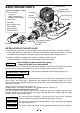
Glow plug No.8 BASIC ENGINE PARTS Cylinder Head Accessories •EC-2 Assembly •Y harness •Duble-sided spongebacked cushioning tape •Check Valve •Fuel Filter •Driver to push Limit Setting Switch •Glow plug No.
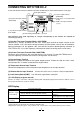
CONNECTING WITH THE EC-2 Connect the receiver and servo-related components (rudder section) in the same manner as in the past. (8) Integrated Buzzer (3) Injector output terminal (INJECTOR) (4) Temperature sensor input terminal (Temp) (5) RPM sensor input terminal (r.p.m.) (2) Injection trim input terminal (AUX:TRIM) (1) Injection time input terminal (CH3:THRO) (6) Limit Setting Switch(LIMIT) (7) L.E.D.
(8) Integrated Buzzer Buzzer sounds when setting Limit, dial is set nnetral a error happens. Buzzer notes and status Notes Status Nil Normal One note (Pi) Limit at Low is set Two successive notes (PiPi) Dial neutral Limit at High is set *Repeated one note (Pi...Pi...) Temperature Sensor is disconnected *Repeated two successive notes (PiPi...PiPi...) Error on setting Limit *Repeated three successive notes (PiPiPi...PiPiPi...) Battery voltage falls down (below 3.
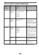
LIST OF 160FX-FI USAGE CONDITIONS Part Name Manufacturer Silencer O.S. *E-5010 Glow plug O.S. *No.8 Propeller Commercially available high-quality product General references: * 17x12 (Basic propeller) Remarks Maximun speed should be between 7,300 and 8,500 rpm. 16x12-14 16.
BEFORE INSTALLING THE ENGINE In addition to the general tools, the following tools are convenient to use. • 14-17mm open end wrench • Large capacity electric starter and battery • Hex wrench to secure the silencer (supplied with the engine) INSTALLING THE GLOW PLUG Carefully insert plug, with washer, fingertight only, before final tightening with the correct size plug wrench.
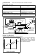
How to fasten the mounting screws. 5mm steel nuts Spring washer or lock washer Steel washer Fig.5 Tighten second nut firmly down onto first nut. 5mm steel Allen screw Tighten this nut first. Spring washer Hardwood such as cherry or maple. 5mm steel screw O.S. radial motor mount (cast aluminum) Hardwood mounting beams A soft engine mount is recommended but should be made of firm enough meterial to prevent excessive engine movement but still minimize engine vibration.
(4) EC-2 Install the EC-2 in a location that is not susceptible to the effects of heat, fuel or vibrations while allowing easy manipulation. Always make sure to attach double-sided, sponge-backed cushioning tape or Velcro tape between the airframe and EC-2 as measures against vibrations. (5) INSTALLATION OF SILENCER (MUFFLER) To fit the standard silencer 1. Fix the exhaust adaptor plate to the engine with the two M5 x15 Allen screws supplied. 2.
LINKAGE AND INITIAL SETTINGS Call up the ATV menu on the condition menu and select THR. Confirm that it is in the center of the throttle curve when the stick is in the center position. Then align the mark in the center of the air valve at that point. The center of the curve is the center, and if the stick is shifted out of position, give priority to the center of the throttle curve. Throttle opening Ensuring a proper linkage is important in the 160RX FI system in terms of a proper air-fuel mixture.
(5) Engine Cutoff Adjustment When using a transmitter equipped with an engine cutoff function, switch the transmitter to the engine cutoff position and adjust the air valve so that it is fully closed at that time. Confirm that the servo is not subjected to an excessive load due to pulling. (6) Confirmation of Throttle and Air Valve Operation When the stick is in the slow position: The rotor mark should be located at the slow mark of the body.
Note: This injection system was developed for use in model airplanes. All adjustments are not performed automatically. Always make sure to check the contents of adjustments prior to use. ENGINE STARTING (RPM shown are with the standard setting.) *Basic setting It is suggested to start with this setting. General reference for engine speed Case of a 17 x 12, 2-blade propeller Full slow engine speed 1,700~1,800r.p.m. Intermediate slow engine speed 6,100~6,300r.p.m.
*This engine employs pressurized fuel feed system, applying high pressure to the fuel tank from the crankcase. When starting first time or starting after long, storage or starting in winter when the temperature is less than 100C, it makes a start easy to apply an electric starter for about 5 to 10 seconds without connecting the plug battery. (1) Always be sure to close the throttle stick to idle position before applying the starter and starting battery.
FLIGHT ADJUSTMENT The next step is to take the airplane on an actual flight. Although the adjustments have been already made, recheck the Limit setting. Put the throttle stick in the slow position and after starting the engine and allowing it to warm up, check the stability of engine speed in the slow position (by confirming that the engine does not stall) and try flying the airplane. After taking off, fly level for several minutes. Next, repeat flying level in a straight line at full speed.
GLOWPLUGS Since the compatibility of glowplug and fuel may have a marked effect on performance and reliability, it may be worthwhile to choose the R/C type plug found most suitable after tests. O.S. No.8 plug is supplied with the engine. Recommended O.S. plug are No.8 and Type F is suitable to use for richer mixture. Carefully install plug finger-tight, before final tightening with the correct size plug wrench. The role of the glowplug With a glowplug engine, ignition is initiated by the application of a 1.
TROUBLESHOOTING Problem Engine does not start Confirmation • Is the power turned on? • Are the connectors securely connected? • Is the lead wire broken? • Is the plug burned out? • Has Limit been set? • Are the connections correct? • Recheck the Buzzer sounds and LED display.
ENGINE & INJECTOR AIR VALVE EXPLODED VIEW C.M3✕8 C.M3✕18 1 2 3 1 4 6 5 2 C.M2.6✕8 7 3 6 4 5 o y 7 e w 8 q - i = C.
ENGINE PARTS LIST No. Code No.
THREE VIEW DRAWING Dimensions(mm) Specifications ■ Displacement ■ Bore ■ Stroke ■ PracticalR.P.M. ■ Output ■ Weight ■ Silencer 26.23 cc(1.60cu.in.) 33.6 mm(1.323in) 29.6 mm(1.165in) 1,800~9,000 r.p.m. 3.7 ps / 8,500r.p.m. 945g (33.3oz.) E-5010 (300g 10.6oz) 65 30 22 2-M5X0.8 64 22 80 96.7 50.5 UNF3/8-24 115.5 51.5 74 120.6 22 123.2 4-φ5.
O.S. GENUINE PARTS & ACCESSORIES ■ O.S.GLOW PLUG No.
MEMO 24
UALITY PRECISION & PERF ORM AN NC E UN ES ED Q CE L UAL EQ TAB L IS H IN G T H E STA N D A R D S O F EXCE LLE 6-15 3-Chome Imagawa Higashisumiyoshi-ku Osaka 546-0003, Japan TEL. (06) 6702-0225 FAX. (06) 6704-2722 URL : http://www.os-engines.co.jp C Copyright 2001 by O.S.Engines Mfg. Co., Ltd. All rights reserved. Printed in Japan.